Method for driving liquid crystal display device

A technology of a liquid crystal display device and a driving method, which is applied to static indicators, optics, instruments, etc., can solve problems such as low image quality, and achieve the effects of suppressing the reduction of image quality and suppressing color separation

Inactive Publication Date: 2013-03-27
SEMICON ENERGY LAB CO LTD
View PDF12 Cites 2 Cited by
  • Summary
  • Abstract
  • Description
  • Claims
  • Application Information

AI Technical Summary

Problems solved by technology

[0009] Existing liquid crystal display devices capable of displaying quasi-3D images have a problem of low image quality

Method used


Image

  • Method for driving liquid crystal display device
  • Method for driving liquid crystal display device
  • Method for driving liquid crystal display device

Examples


Embodiment approach 1

[0030] In this embodiment, an example of a liquid crystal display device that displays an image by switching between a right-eye image and a left-eye image will be described.

[0031] Below, refer to Figures 1A to 1C An example of the liquid crystal display device in this embodiment will be described. Figures 1A to 1C An example of the liquid crystal display device in this embodiment is shown.

[0032] First, refer to Figure 1A A configuration example of the liquid crystal display device in this embodiment will be described. Figure 1A It is a schematic diagram showing a configuration example of the liquid crystal display device in Embodiment 1. FIG.

[0033] Figure 1A The illustrated liquid crystal display device includes a display selection signal output circuit (also referred to as DSELOUT) 101 , a display data signal output circuit (also referred to as DDOUT) 102 , a lamp unit 104 and a plurality of display circuits (also referred to as DISP) 105 .

[0034] The disp...

Embodiment approach 2

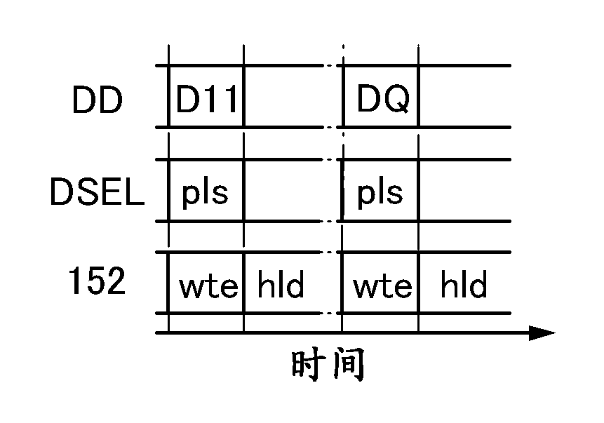
[0093] In this embodiment mode, an example of a shift register included in the display selection signal output circuit in the liquid crystal display device of the above-mentioned embodiment mode will be described. Note that the shift register described in this embodiment is just an example, and the structure of the shift register that can be applied to the display selection signal output circuit in the liquid crystal display device of the above-mentioned embodiment is not limited to the shift register described in this embodiment. register. Shift registers with other structures and circuits other than the shift register (such as decoders, etc.) can also be applied to the display selection signal output circuit in the liquid crystal display device of the above-mentioned embodiment.

[0094] An example of the shift register of this embodiment includes a multi-stage sequential circuit (also referred to as FF).

[0095] Below, refer to Figure 2A with 2B Illustrates one of many...

Embodiment approach 3

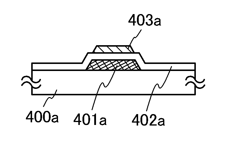
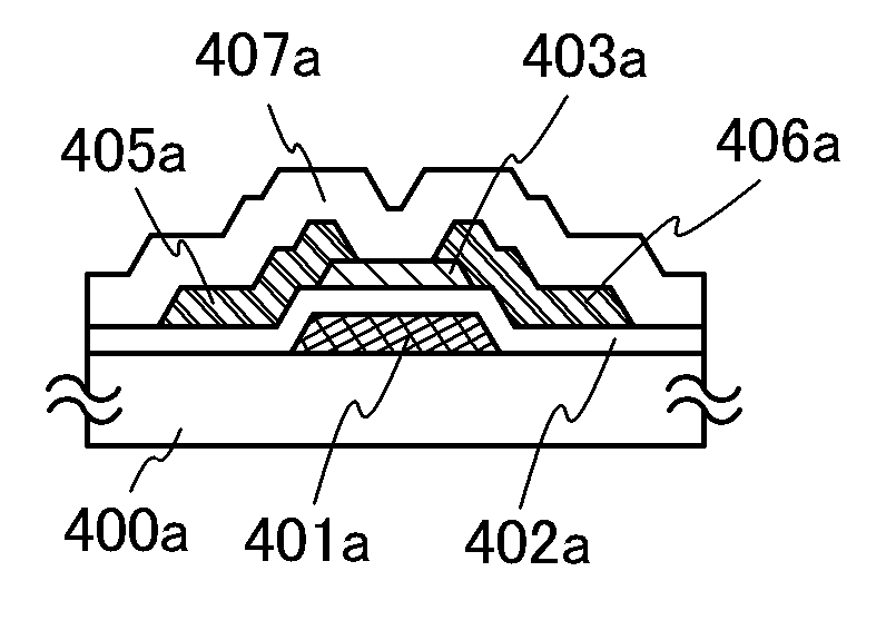
[0151] In this embodiment mode, an example of a display circuit in the liquid crystal display device described in the above-mentioned embodiment mode will be described.

[0152] Below, refer to Figure 4A with 4B An example of a display circuit in this embodiment will be described. Figure 4A with 4B It is a figure for demonstrating the example of the display circuit in this embodiment.

[0153] First, refer to Figure 4A A configuration example of the display circuit in this embodiment will be described. Figure 4A A configuration example of the display circuit in this embodiment is shown.

[0154] Figure 4A The display circuit shown includes a transistor 151 , a liquid crystal element 152 and a capacitor 153 .

[0155] exist Figure 4A In the display circuit in , the transistor 151 is a field effect transistor.

[0156] In addition, in the liquid crystal display device, the liquid crystal element includes a first display electrode, a second display electrode, and a...


PUM

PropertyMeasurementUnit
electrical resistivityaaaaaaaaaa
transmittivityaaaaaaaaaa

Abstract

Data of display data signals input to a plurality of display circuits are alternately switched between an image data for the left eye and an image data for the right eye every a plurality of frame periods; the plurality of display circuits are divided into a plurality of groups each including the display circuits in at least one row, and in each group, pulses of display selection signals are sequentially input Z (Z is a natural number greater than or equal to 3) times to the display circuits in the respective rows; and data of the display data signal input during a K-th (K is a natural number greater than or equal to 2) frame period and data of the display data signal input during a (K-1)-th frame period are compared. As a result, a color image and a black image are selectively displayed.

Description

technical field [0001] Embodiments of the present invention relate to a method of driving a liquid crystal display device. Background technique [0002] In recent years, research and development has been conducted on liquid crystal display devices capable of displaying pseudo 3D images. [0003] Examples of the aforementioned liquid crystal display device capable of displaying a pseudo-3D image include a liquid crystal display device that causes a viewer to view a two-dimensional (2D) image as a 3D image using parallax between left and right eyes. In the above example of the liquid crystal display device, an image for the left eye (hereinafter also referred to as left-eye image) and an image for the right eye (hereinafter also referred to as right-eye image) are alternately displayed on the pixel portion, and the viewer The above images are viewed using glasses equipped with polarization shutters including liquid crystals for the left and right eyes. When the image for the...

Claims


Application Information

Patent Timeline
Patent Type & Authority Applications(China)
IPC IPC(8): G09G3/36G02F1/133G02F1/1368G09G3/20G09G3/34
CPCG09G3/20G02F1/00G02F1/1368H04N13/0422H04N13/04G09G2310/0235G09G3/3688G09G3/34G02F1/133G09G2310/0286G09G2320/0209G09G3/36G09G2310/063G09G3/003H04N13/0438H04N13/341H04N13/324
Inventor 小山润山崎舜平
Owner SEMICON ENERGY LAB CO LTD
Why Eureka
Try Eureka