Method and device for controlling a multi-phase electronically commutated electric machine and a motor system

一种电子换向、相电压的技术,应用在电子换向电动机控制、电子换向器、控制系统等方向,达到力矩波动降低、径向力激励降低、噪声产生小的效果

Active Publication Date: 2013-03-27
ROBERT BOSCH GMBH
View PDF5 Cites 9 Cited by
  • Summary
  • Abstract
  • Description
  • Claims
  • Application Information

AI Technical Summary

Problems solved by technology

The resulting torque fluctuations (Momentenrippel) and radial force excitation lead to clearly perceptible noise

Method used


Image

  • Method and device for controlling a multi-phase electronically commutated electric machine and a motor system
  • Method and device for controlling a multi-phase electronically commutated electric machine and a motor system
  • Method and device for controlling a multi-phase electronically commutated electric machine and a motor system

Examples


Embodiment Construction

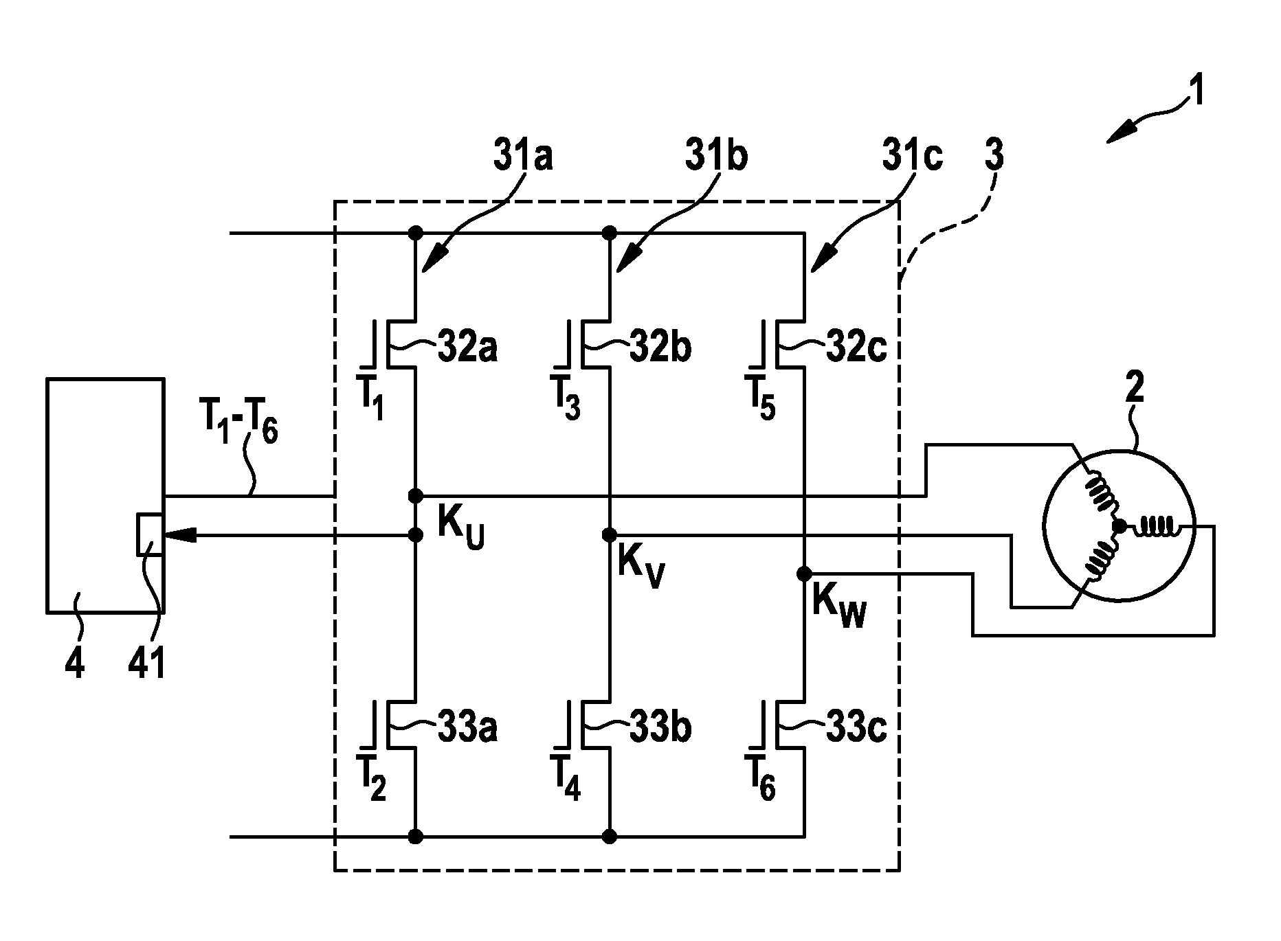
[0032] figure 1 The motor system 1 with the motor 2 is shown. The motor 2 is electronically commutated, that is, an alternating phase voltage is applied to a phase branch, for example, to a stator that includes one or more coil windings, not shown, so as to drive the rotor of the motor 2. For example, the electric machine 2 is constructed in the form of a synchronous motor, an asynchronous motor, or in other comparable ways. In the illustrated embodiment, the electric machine 2 is a synchronous motor with three phase branches including coil windings wired in a star connection around the stator teeth.

[0033] The synchronous motor 2 is controlled by the driving circuit 3. The drive circuit 3 provides three phase terminals K for this purpose U , K V And K W , Wherein the respective phase voltage potentials are applied to the phase terminals. Provided at the phase terminal K by the respective inverter circuit 31 U , K V And K W The phase voltage potential at.

[0034] Each of the ...


PUM


Abstract

The invention relates to a method for operating an electronically commutated electric machine (2). Alternating phase voltage potentials are applied to the phase conductors of the electric machine (2) for commutation, said phase voltage potentials being generated by a pulse-width modulation so that the height of the applied phase voltage potential is determined by a duty cycle (TV) of the pulse width modulation. In order to determine an instant of a zero crossing of a current induced in a phase conductor, a blanking interval (AT) which represents a time slot, is provided, when no phase current potential is applied to the corresponding phase conductor. A first transition time slot (uT1) is provided prior to and / or after the blanking interval (AT) during which the progression of the applied phase voltage potential has a defined first gradient during.

Description

Technical field [0001] The present invention relates to an electronically commutated motor, wherein a phase voltage is applied to the electronically commutated motor in order to drive the motor. The invention furthermore relates to a method for sensorless detection of the rotor position of an electric machine. Background technique [0002] Multiphase electronically commutated motors, especially synchronous motors, can be driven, for example, by providing a stator magnetic field that leads the excitation magnetic field provided by the rotor. The stator magnetic field is generated by applying a phase voltage to the phase branch of the motor stator, especially the direction and strength of the stator magnetic field. [0003] In order to determine the lead of the stator magnetic field, the rotor position of the motor rotor needs to be known. Often in the case of such motors, in order to save position sensors, the rotor position is determined sensorlessly. One possible method consist...

Claims


Application Information

Patent Timeline
Patent Type & Authority Applications(China)
IPC IPC(8): H02P6/00H02P6/18H02P6/08
CPCH02P6/182H02P6/002H02P6/085H02P6/28
Inventor G.克内希特
Owner ROBERT BOSCH GMBH
Why Eureka
Try Eureka