
High-speed rescue boat lowering device

A rescue boat, landing technology, applied in the direction of the lifting device, etc., can solve the problems of people in distress, swaying rescue boats, poor stability, etc., and achieve the effect of high safety factor, reducing swaying, and increasing stability

Active Publication Date: 2013-04-03
JIANGYIN BEIHAI LSA
View PDF8 Cites 8 Cited by
  • Summary
  • Abstract
  • Description
  • Claims
  • Application Information

AI Technical Summary

Problems solved by technology

[0002] Rescue boats are usually used as an escape tool for the crew when large ships are in distress. At present, most rescue boat launching devices include a boom frame, a boom hinged with the boom frame, a retractable device, and a The traction cable on the retractable device and the several guide wheels arranged on the boom frame, the traction cable is connected between the several guide wheels and the hook on the rescue boat , the above structure has the following disadvantages: 1. In the process of landing, due to the insufficient rigidity of the tow rope, the rescue boat will sway or even rotate during the landing process, causing the distressed people to be bumped again; 2. When the boat falls to the water surface, the rescue boat will heave up and down with the waves, the stability is poor, and it may cause secondary injuries to the victims, and the safety factor is poor

Method used


Image

  • High-speed rescue boat lowering device
  • High-speed rescue boat lowering device
  • High-speed rescue boat lowering device

Examples


Embodiment Construction

[0021] The specific implementation manners of the present invention will be further described below in conjunction with the drawings and examples. The following examples are only used to illustrate the technical solution of the present invention more clearly, but not to limit the protection scope of the present invention.

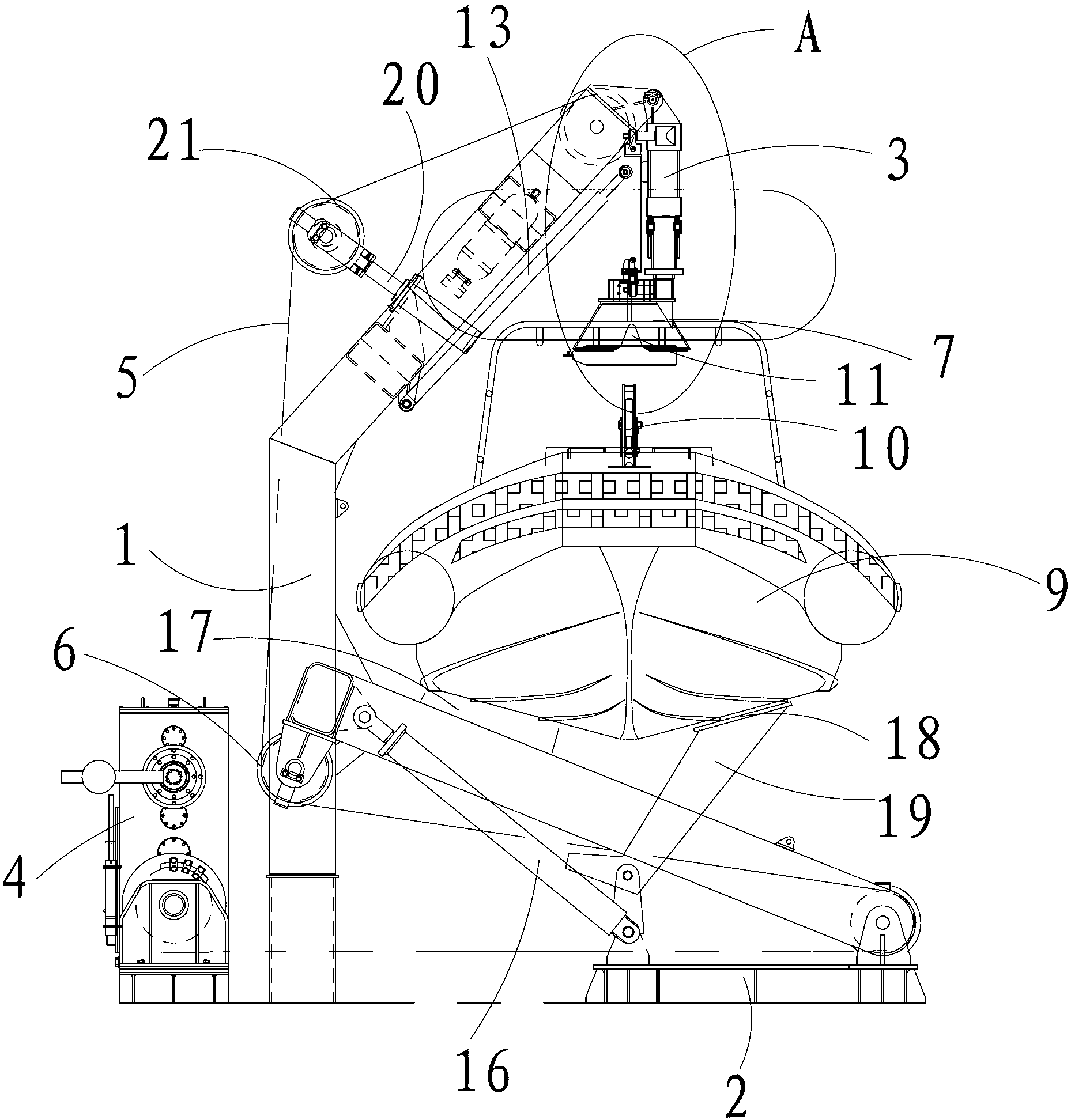
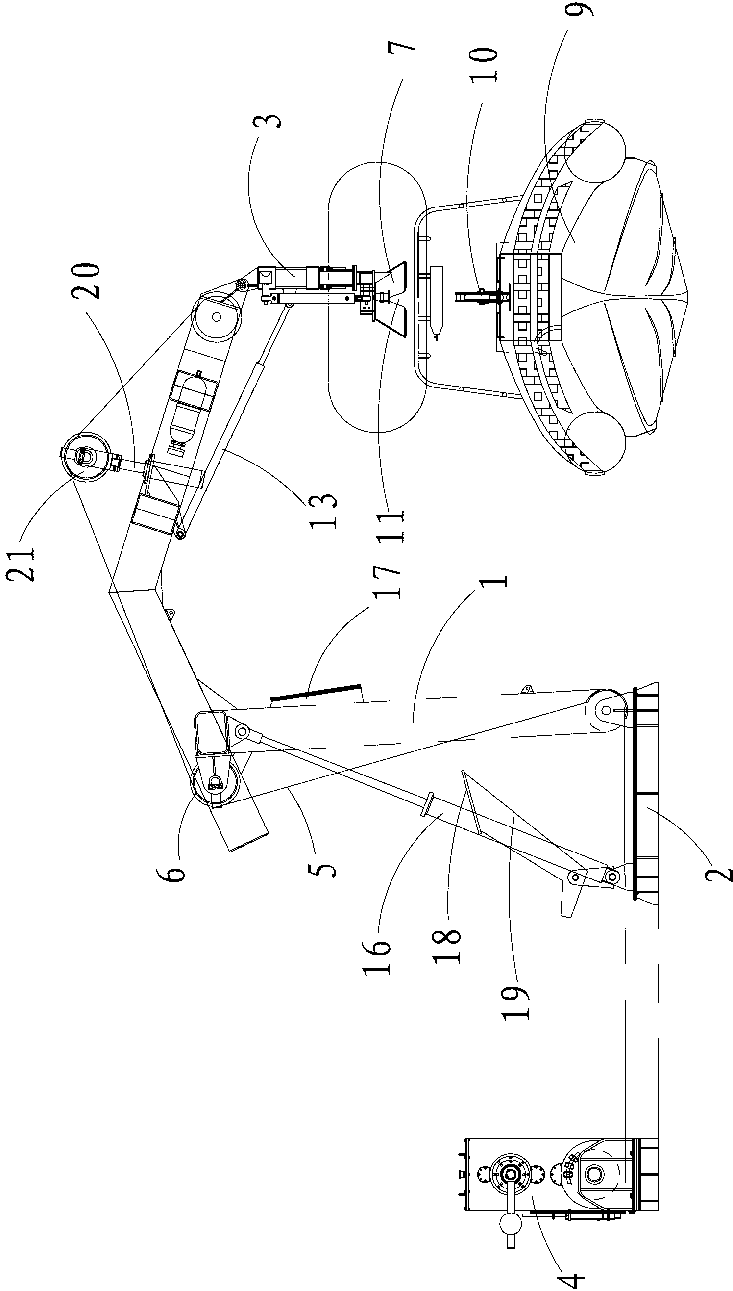
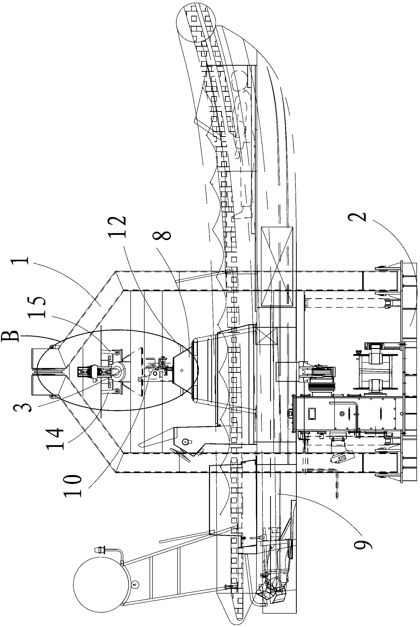
[0022] Such as Figure 1-Figure 4 As shown, a high-speed rescue boat launching device includes a boom frame, a boom 3 whose upper end is hinged to the upper end of the boom frame, a traction cable 5 wound around a winch 4, and a rotating device Several guide wheels 6 on the boom frame, the first connecting part 7 fixedly arranged on the lower end of the boom 3, the second connecting part 8 fixedly arranged on the rescue boat 9, and the second connecting part 8 fixedly arranged on the The hook 10 on the second connecting part 8, the first connecting part 7 has an inner cavity, the second connecting part 8 is matched with the inner cavity, and the first conn...


PUM


Abstract

The invention discloses a high-speed rescue boat lowering device. The device comprises a lifting arm frame, a lifting arm, pulling cables, a plurality of guide wheels, a first connecting part, a second connecting part and a hook, wherein the lifting arm is hinged with the lifting arm frame; the guide wheels are hinged to the lifting arm frame; the first connecting part is fixedly arranged on the lower end part of the lifting arm; the second connecting part is used for being connected with a rescue boat; the hook is fixedly arranged on the second connecting part; the first connecting part is provided with an inner cavity; the second connecting part is matched with the inner cavity; clamping grooves which are opened downwards are formed in the first connecting part; positioning rods are fixedly arranged on the second connecting part; the positioning rods are matched with the clamping grooves; an adjusting mechanism is arranged between the lifting arm frame and the lifting arm; the lifting arm frame and the lifting arm are matched through the first connecting part on the lifting arm and the second connecting part on the rescue boat; and the first connecting part and the second connecting part are matched through the clamping grooves and the positioning rods to form a rigid body. Swing is reduced in a rescue boat lowering process and a wave compensation effect can be achieved when the rescue boat falls onto the water surface, the rescue boat stably falls onto the water surface, the safety factor is high, and the stability is further improved because the adjusting mechanism for adjusting the verticality and the levelness is arranged.

Description

technical field [0001] The invention relates to a high-speed rescue boat launching device. Background technique [0002] Rescue boats are usually used as an escape tool for the crew when large ships are in distress. At present, most rescue boat launching devices include a boom frame, a boom hinged with the boom frame, a retractable device, and a The traction cable on the retractable device and the several guide wheels arranged on the boom frame, the traction cable is connected between the several guide wheels and the hook on the rescue boat , the above structure has the following disadvantages: 1. In the process of landing, due to the insufficient rigidity of the tow rope, the rescue boat will sway or even rotate during the landing process, causing the distressed people to be bumped again; 2. When the boat falls to the water surface, the rescue boat will heave up and down with the waves, the stability is poor, and it may cause secondary injuries to the victims, and the safe...

Claims


Application Information

Patent Timeline
IPC IPC(8): B63B23/48
Inventor 顾中达
Owner JIANGYIN BEIHAI LSA
Learn More