Rigid connectors for sandwich shear wall structures
A technology of connectors and shear walls, which is applied in the direction of walls, building components, building structures, etc., can solve the problems of cumbersome construction, high cost, and complicated process, and achieve the effect of overall excellent structure, low cost, and reliable force transmission
- Summary
- Abstract
- Description
- Claims
- Application Information
AI Technical Summary
Problems solved by technology
Method used
Image
Examples
Embodiment 1
[0024] Example 1. Just connect the connector
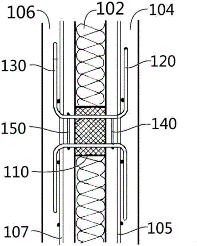
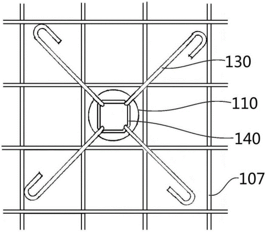
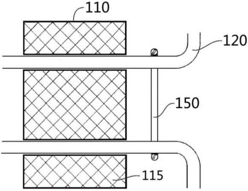
[0025] Such as Figures 1A to 2B As shown, the rigid connector of this embodiment includes: an anchor seat 110, which passes through and is fixed to the sandwich layer 102 of the sandwich shear wall; an inner anchor bar 120, on the one hand, is fastened to the anchor The seat 110 on the other hand extends towards the direction of the inner leaf wall, and the extension part of the inner anchor tendon forms a bend at the cavity 104 which basically passes through the inner leaf wall so as to be parallel to the surface of the inner leaf wall And protrude substantially radially with respect to the anchor seat 110; the outer anchor rib 130 is fastened to the anchor seat 110 on the one hand and extends toward the direction of the outer leaf wall on the other hand, and the outer anchor rib 130 The extension portion of 130 is bent at the cavity 106 substantially passing through the outer leaf wall to extend parallel to the surface of the ...
Embodiment 2
[0039] Example 2. Rigid connectors are used in the construction of inner walls of sandwich shear wall structures
[0040] image 3 It is shown that the rigid joint connector of the present invention is used for the installation of the inner wall of the sandwich shear wall structure.
[0041] The figure schematically shows the installation position of the rigid connector described in Embodiment 1 (shown as S100 in the figure) used in the inner wall construction of the sandwich shear wall structure. In addition, other components or structures are also described in the figure, such as: foundation ground beam S220, wall reserved connection reinforcement S310, reinforcement welded mesh S320, cast-in-place ring beam S330, wall reinforcement welded mesh lower mesh overlap S340, The reserved length of the lower net overlap is S350, the polystyrene foam is S420, and the concrete is sprayed.
PUM
 Abstract
Description
Claims
Application Information
 - R&D
- Intellectual Property
- Life Sciences
- Materials
- Tech Scout
- Unparalleled Data Quality
- Higher Quality Content
- 60% Fewer Hallucinations
Browse by: Latest US Patents, China's latest patents, Technical Efficacy Thesaurus, Application Domain, Technology Topic, Popular Technical Reports.
© 2025 PatSnap. All rights reserved.Legal|Privacy policy|Modern Slavery Act Transparency Statement|Sitemap|About US| Contact US: help@patsnap.com


