
Universal flexible interconnection large floating connector

A floating connector and flexible interconnection technology, applied in the direction of connection, connecting device parts, contact parts, etc., can solve the problem of inability to achieve large-scale axial floating, errors between metal panels and connectors, and increase the cost of elastic needle manufacturing and other problems, to achieve the effect of stable and reliable elastic modulus, stable and reliable performance, and reliable structural performance.

Pending Publication Date: 2022-03-01
CHINA AVIATION OPTICAL-ELECTRICAL TECH CO LTD
View PDF10 Cites 0 Cited by
  • Summary
  • Abstract
  • Description
  • Claims
  • Application Information

AI Technical Summary

Problems solved by technology

After the backplane connector is welded on the filter backplane, when it cooperates with the metal panel as a whole, there will be a problem: the relative position of the metal panel and the connector must be within ±0.2mm, especially on the panel. is more serious when the number of connectors is relatively large
[0005] Secondly, the current elastic needle structure cannot achieve a wide range of axial floating. The current elastic needle technology can only achieve ±0.5mm axial floating. Higher axial floating requirements will increase the reliability of the elastic needle
[0006] Finally, in the technical solution of the elastic needle, to maintain the reliability and axial floating ability of the elastic needle, the elastic needle contact must be designed to be relatively long and have a large diameter to ensure function and reliability, which will undoubtedly increase the elastic needle. production cost, cannot be universally used in connectors

Method used


Image

  • Universal flexible interconnection large floating connector
  • Universal flexible interconnection large floating connector
  • Universal flexible interconnection large floating connector

Examples


Embodiment Construction

[0071] In order to further explain the technical means and effects of the present invention to achieve the intended purpose of the invention, the specific implementation and structure of the universal flexible interconnection large floating connector proposed according to the present invention will be described below in conjunction with the accompanying drawings and preferred embodiments. , features and their effects are described in detail below.

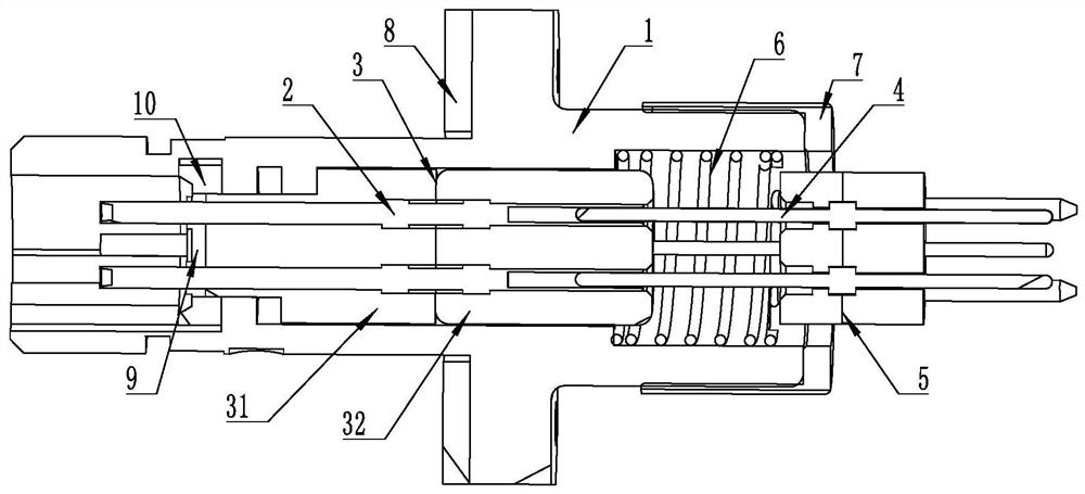
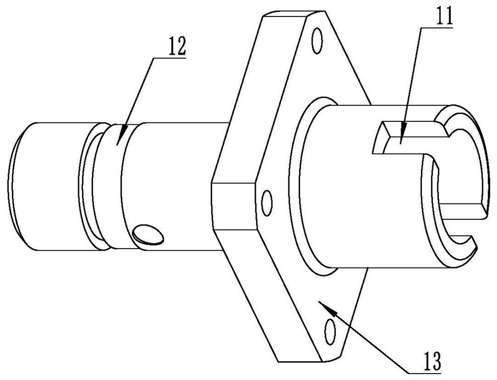
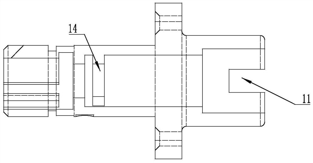
[0072] see Figure 1-11 , which is a schematic diagram of the structure of each part of the universal flexible interconnection large floating connector of the present invention, the connector includes an integral circular housing 1, and the outer periphery of the front end of the housing 1 is provided with a colored color for displaying that the connector is mated in place. Marking groove 12, the outer periphery of the housing 1 is also provided with a square disc housing 13 for realizing the fixing of the connector, and a conducti...


PUM


Abstract

The invention relates to a universal flexible interconnection large floating connector which comprises a circular shell, a front insulator fixedly assembled at the front end of the circular shell and a rear insulator slidably assembled at the rear end of the circular shell, wherein a radial floating gap is formed between the rear insulator and the circular shell. An axial pre-tightening spring for enabling the rear insulator to be far away from the front insulator is also arranged in the circular shell; in the sliding stroke of the rear insulator, the pin at the front end of the rear contact assembled in the rear insulator and the jack at the rear end of the front contact assembled in the front insulator are always in plugging conduction; the contact pin at the front end of the rear contact element is a radial flexible floating contact pin which can realize radial floating through bending. According to the connector, the multi-stage conversion modular design and the flexible bending contact piece mode are adopted to achieve the large-range stepless floating effect in the axial direction and the radial direction at the same time, the structural performance is reliable, the part structure is simple, and subsequent series pedigree development of the connector and overall printed board welding and packaging of the connector are facilitated.

Description

technical field [0001] The invention belongs to the technical field of connectors, in particular to a universal flexible interconnection large floating connector. Background technique [0002] At present, there are many types of electrical connectors, and their application range is very wide. In particular, the fire control chassis and information processing chassis that are widely used in the new generation of tanks or radar platforms, the filter panel structure of the box has been more and more reflected and applied. The structural design of the filter panel specifically includes several parts, the filter backplane, the backplane connector (including circular and rectangular connectors) and the metal panel. After the backplane connector is welded on the filter backplane, when it cooperates with the metal panel as a whole, there will be a problem: the relative position of the metal panel and the connector must be within ±0.2mm, especially on the panel. It is more serious ...

Claims


Application Information

Patent Timeline
Patent Type & Authority Applications(China)
IPC IPC(8): H01R13/24H01R13/40H01R13/631H01R13/02
CPCH01R13/24H01R13/40H01R13/6315H01R13/02
Inventor 杨尚矗胡晓松宋峥李跃文
Owner CHINA AVIATION OPTICAL-ELECTRICAL TECH CO LTD
Learn More