Device for pneumatic emergency switch valve

An emergency switch, pneumatic technology, used in valve devices, valve operation/release devices, valve details, etc.

Inactive Publication Date: 2015-03-04
张小良
View PDF6 Cites 0 Cited by
  • Summary
  • Abstract
  • Description
  • Claims
  • Application Information

AI Technical Summary

Problems solved by technology

[0003] At present, there is no device that can quickly improve efficiency for emergency switch valves

Method used


Image

  • Device for pneumatic emergency switch valve
  • Device for pneumatic emergency switch valve
  • Device for pneumatic emergency switch valve

Examples


Embodiment 1

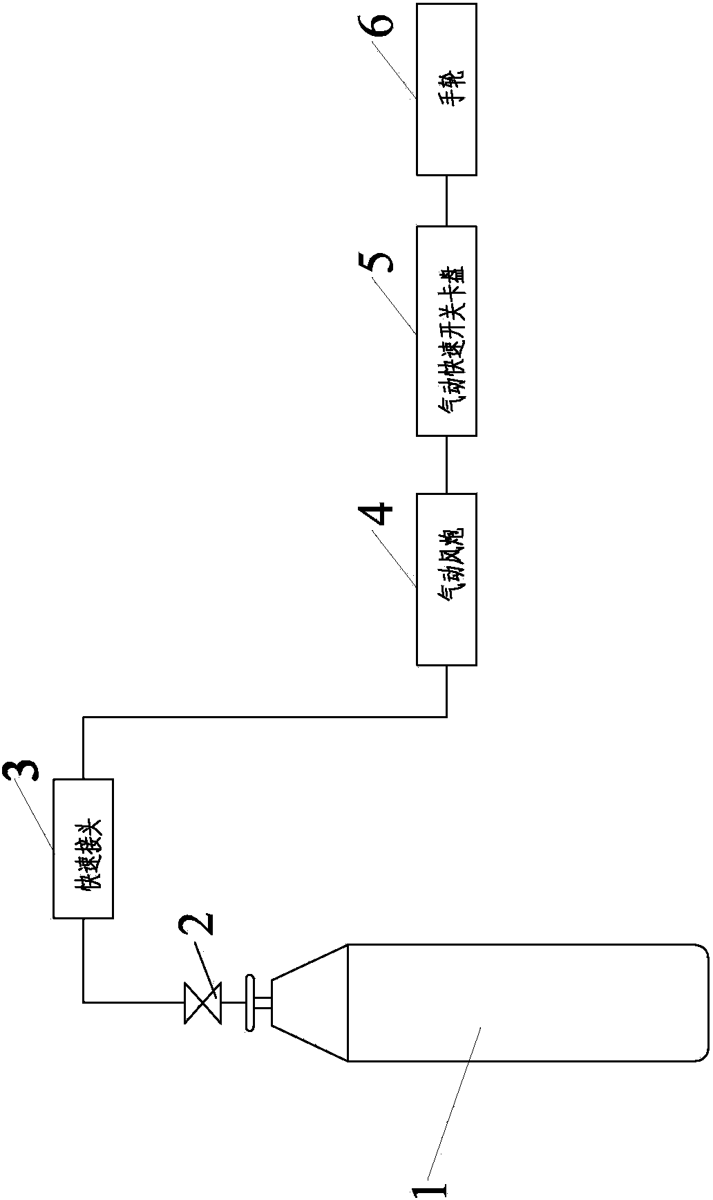
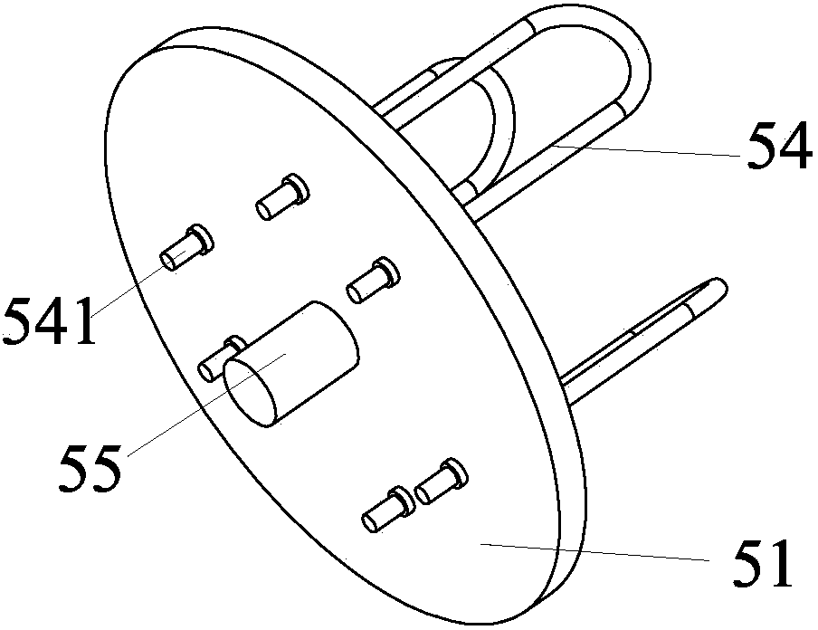
[0034] One of the specific implementations of a device for a pneumatic emergency switch valve of the present application, such as figure 1 As shown, it includes a high-pressure resistant gas cylinder 1, a pressure reducing valve 2, a quick connector group 3, a pneumatic wind gun 4 and a pneumatic quick switch chuck 5 for pneumatically clamping with the handwheel 6; the high-pressure resistant gas cylinder 1 One end of the pressure reducing valve 2 is connected to one end of the pressure reducing valve 2 through a high pressure resistant air pipe, the other end of the pressure reducing valve 2 is connected to one end of the quick connector group 3 through a high pressure resistant air pipe, and the other end of the quick connector group 3 One end of the pneumatic wind gun 4 is connected with a high-pressure resistant air pipe, and the other end of the pneumatic wind gun 4 is connected with the air gun connector 55 of the pneumatic quick switch chuck 5 . Compared with the prior ...

Embodiment 2

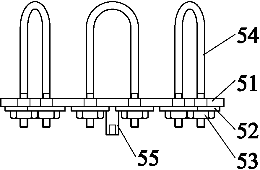
[0040] The second specific embodiment of a device for a pneumatic emergency switch valve of the present application, the main technical solution of this embodiment is the same as that of embodiment 1, and the features not explained in this embodiment are explained in embodiment 1. This will not be repeated here. The difference between this embodiment and Embodiment 1 is that there are two groups of screw holes 511 located on the upper semicircle of the main plate 51, which are respectively the first screw hole and the second screw hole, and the first screw hole and the second screw hole are both Long holes, and the first screw hole and the second screw hole are centrally symmetrically arranged, and the screw hole 511 located in the lower semicircle of the main plate 51 is provided with a group, specifically the third screw hole, the third screw hole is a round hole, and the The third screw hole is arranged in the middle of the arc of the lower semicircle. The clamping effect ...


PUM


Abstract

The invention discloses a device for a pneumatic emergency switch valve. The device comprises a high-pressure-resistant gas cylinder, a pressure reducing valve, a rapid joint group, a pneumatic jackhammer and a pneumatic rapid switch chuck, wherein the pneumatic rapid switch chuck is pneumatically clamped with a hand wheel; one end of the high-pressure-resistant gas cylinder is connected with one end of the pressure reducing valve through a high-pressure-resistant gas tube; the other end of the pressure reducing valve is connected with one end of the rapid joint group through a high-pressure-resistant gas tube; the other end of the rapid joint group is connected with one end of the pneumatic jackhammer through a high-pressure-resistant gas tube; and the other end of the pneumatic jackhammer is connected with a pneumatic gun joint of the pneumatic rapid switch chuck. Compared with the prior art, the device has the advantages that the device can be operated by a single person, has low requirements on matched equipment, is easy to operate, and has high working environment adaptability; and meanwhile, the valve switch-on / off efficiency is high, high safety can be realized, and the device is convenient to carry.

Description

technical field [0001] This application relates to the engineering technology of special mechanical equipment for petrochemical industry, in particular to a device for pneumatic emergency switching valves. Background technique [0002] The petrochemical industry mostly adopts electric or pneumatic mode for the opening and closing of large valves. When encountering the "four stop" accidents (stop wind, power, water, and steam), only rely on the small handwheel to switch the large valve in an emergency. This method is not only inefficient, but also takes a long time Handling poses great risks. [0003] At present, there is no device that can quickly improve efficiency and carry out emergency switching valves. [0004] Therefore, it is particularly important to develop a system device for a pneumatic emergency switch valve. Contents of the invention [0005] The purpose of this application is to avoid the deficiencies in the prior art and provide a system device for a pneu...

Claims


Application Information

Patent Timeline
Patent Type & Authority Patents(China)
IPC IPC(8): F16K31/14
Inventor 张小良
Owner 张小良
Why Eureka
Try Eureka