Supercharge Your Innovation With Domain-Expert AI Agents!

Heat pipe exchanger with spray pipes

A technology of heat pipe heat exchanger and water spray pipe, which is applied in indirect heat exchangers, cleaning heat transfer devices, lighting and heating equipment, etc. problem, to achieve the effect of good dust removal and safe dust removal environment

Inactive Publication Date: 2013-04-03
郭丰亮
View PDF0 Cites 1 Cited by
  • Summary
  • Abstract
  • Description
  • Claims
  • Application Information

AI Technical Summary

Problems solved by technology

[0004] The technical problem mainly solved by the present invention is to provide a heat pipe heat exchanger with a water spray pipe, which can solve the problems existing in the existing heat pipe heat exchanger dust removal equipment that easily affect the pressure inside the heat exchanger, cause safety hazards, and affect the heat exchanger. Heat pipe life and other issues

Method used


Image

  • Heat pipe exchanger with spray pipes

Examples


Embodiment Construction

[0012] The preferred embodiments of the present invention will be described in detail below in conjunction with the accompanying drawings, so that the advantages and features of the present invention can be more easily understood by those skilled in the art, so as to define the protection scope of the present invention more clearly.

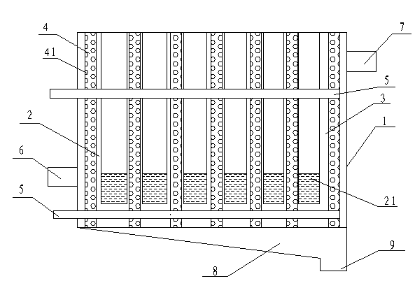
[0013] see figure 1 , the embodiment of the present invention includes: a housing 1, a plurality of heat transfer tubes 2 with one end parallel to the inner upper wall of the housing 1 and with a built-in working medium 21, between the two heat transfer tubes 2 or between the heat transfer tubes 2 and the shell The channel 3 between the bodies 1 is provided with a water spray pipe 4 parallel to the heat transfer pipe 2 , and the water spray pipe 4 is covered with water spray holes 41 for dedusting the heat transfer pipe 2 .

[0014] Further, a water supply pipe 5 is arranged on the upper and lower sides of the casing 1 to connect with the water s...


PUM


Abstract

The invention discloses a heat pipe exchanger with spray pipes. The heat pipe exchanger comprises a shell, a plurality of heat transfer pipes and the spray pipes, wherein the heat transfer pipes are filled with working mediums, one ends of the heat transfer pipes are fixed on the upper wall in the shell in parallel, the spray pipes parallel to the heat transfer pipes are arranged in channels between every two heat transfer pipes or between the heat transfer pipes and the shell, and spray holes are distributed on each spray pipe. With the structure, the heat pipe exchanger with the spray pipes solves the problem that the dust removal apparatus of the conventional heat pipe exchanger is liable to affect the pressure intensity in the exchanger to cause potential safety hazard and affect the service life of a heat exchange tube, and has the advantages of clean dust removal, safety dust removal environment, good dust removal effect, energy conservation, environment friendless and the like.

Description

technical field [0001] The invention relates to the field of heat pipe heat exchangers, in particular to a heat pipe heat exchanger with water spray pipes. Background technique [0002] The heat pipe heat transfer technology uses the phase change cycle of the working fluid in the closed working chamber to transfer heat, so it has the advantages of large heat transfer and high transfer efficiency. Its working principle is: the heat receiving side of the heat pipe absorbs the heat of exhaust gas, and transfers the heat to the working medium in the tube. After absorbing heat, the working medium turns into steam in the form of evaporation and boiling. The steam rises to the heat release side under the action of pressure difference and condenses at the same time. When it becomes liquid, heat is released, and the heat is transferred to the cold fluid on the heat release side, and the condensed liquid flows back to the heat side by gravity. Since the inside of the heat pipe is...

Claims


Application Information

Patent Timeline
Patent Type & Authority Applications(China)
IPC IPC(8): F28D15/02F28G9/00
Inventor 郭丰亮
Owner 郭丰亮
Features
  • R&D
  • Intellectual Property
  • Life Sciences
  • Materials
  • Tech Scout
  • Unparalleled Data Quality
  • Higher Quality Content
  • 60% Fewer Hallucinations
Learn More