
Suspension flow meter with limit value switch

A technology of limit flow and suspension, which is applied in the direction of volume/mass flow generated by mechanical effects, and through detection of dynamic effects of fluid flow, etc., can solve problems such as large limit flow measurement errors and hysteresis, and reduce manufacturing costs and complexity. Sex reduction, cost reduction effect

Active Publication Date: 2013-04-03
KROHNE MESSTECHNICK GMBH & CO KG
View PDF7 Cites 2 Cited by
  • Summary
  • Abstract
  • Description
  • Claims
  • Application Information

AI Technical Summary

Problems solved by technology

However, this type of detection of the limit flow results in a significantly greater measurement error of the limit flow and a significantly greater and thus disadvantageous hysteresis than a detection with an inductive slot starter.

Method used


Image

  • Suspension flow meter with limit value switch
  • Suspension flow meter with limit value switch
  • Suspension flow meter with limit value switch

Examples


Embodiment Construction

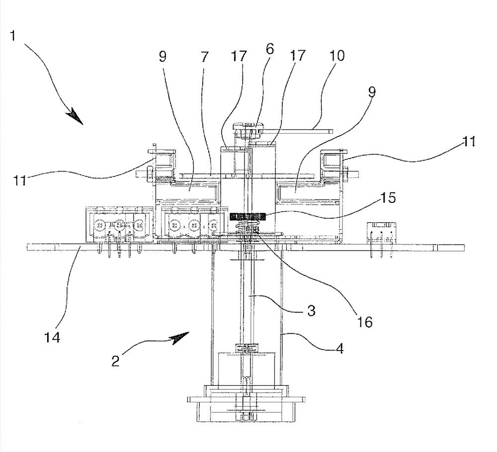
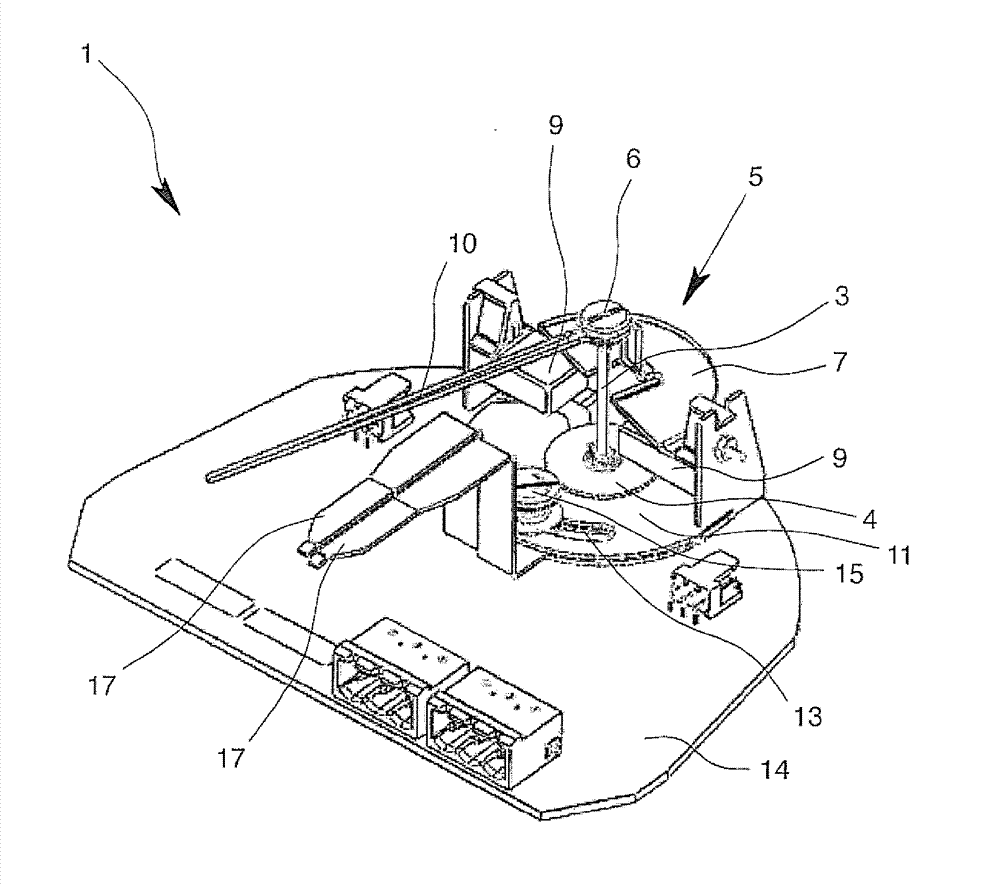
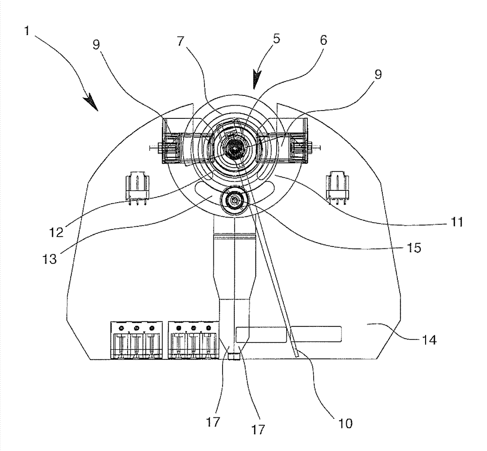
[0022] exist Figures 1 to 4The suspension flowmeter 1 according to the invention is partially shown in , which includes the measuring tube, the suspension and the housing, which are not shown here. The measuring transducer 2 has the shaft 3 as an indicator and detects the deflection of the suspended body, converting this deflection into a corresponding angle of the shaft 3 . In the cylindrical housing 4 of the measuring transducer, a magnet is arranged on the shaft 3 , which is magnetically coupled with a magnet arranged in the suspension, thereby converting the deflection of the suspension into a corresponding angle of the shaft 3 . The shaft 3 is connected to the actuator 5 via a screw connection 6 , wherein the actuator 5 is designed as a small sheet 7 and a ferromagnetic film 8 is pasted on it. When a defined corresponding limit flow is reached, the actuator 5 actuates one of the two reed switches 9 serving as limit value switches. The measured value indicator 10 is als...


PUM


Abstract

The present invention provides a suspension flow meter with a limit value switch (1), which is provided with the following components: suspension which is equipped in a measuring tube and can deflect through fluid flow; a measuring converter (2) which is provided with an indicator (3) and is used for detecting suspension deflection and converting the deflection to a corresponding amount of the indicator (3); at least one trigger (5) and at least one limit value switch (9), wherein the trigger (5) is coupled with the indicator (3). When an utmost flow is reached, the trigger (5) triggers the limit value switch (9). The limit value switch (9) is a reed switch. Therefore the realized suspension flow meter (1) has the following advantages: reduced complicity, low construction expenditure, low manufacturing expenditure, and reduced cost.

Description

technical field [0001] The invention relates to a suspension flow meter for measuring the flow of fluid flowing through a measuring tube, which has: a suspension arranged in the measuring tube which can be deflected by the fluid flow; a suspension with an indicator for detecting the suspension A measuring converter that converts the offset of the body and converts the offset into a correspondingly large offset of the indicator; at least one actuator and at least one limit value switch, wherein the actuator is coupled with the indicator, and when the limit flow is reached, The actuator actuates the limit value switch. Background technique [0002] Suspension flow meters of the type described are used in numerous applications for flow measurement of fluids, which may be gases or liquids, due to their simplicity and robustness. The measuring principle of a suspension flow meter is based on the deflection of a suspension deflected by a flowing fluid, the flow being derived from...

Claims


Application Information

Patent Timeline
Patent Type & Authority Applications(China)
IPC IPC(8): G01F1/24
CPCG01F1/24
Inventor C.佩耶尔
Owner KROHNE MESSTECHNICK GMBH & CO KG
Learn More