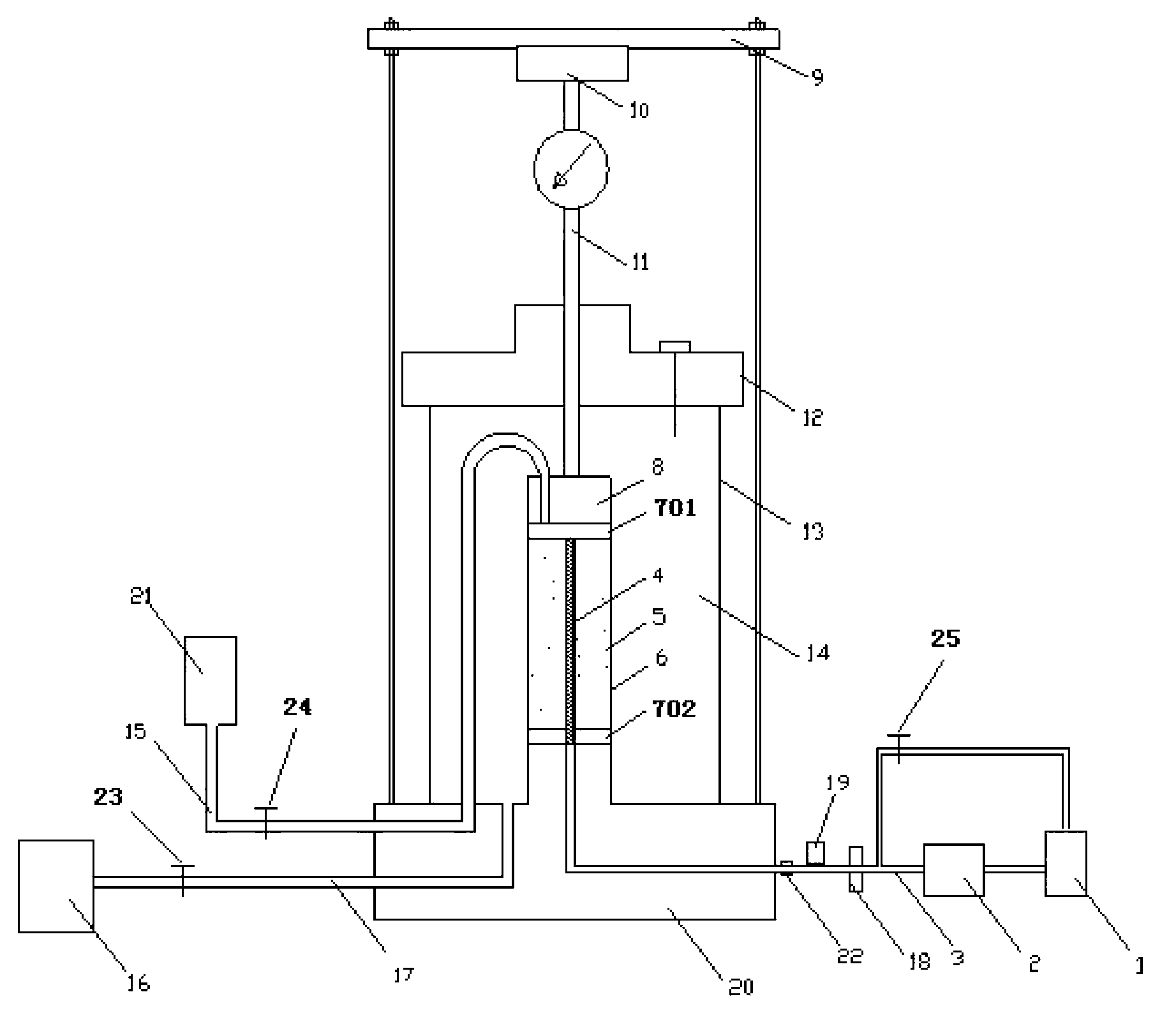
Indoor grouting testing device under simulation of complex stress effect and testing method thereof
A technology of complex stress and test device, applied in measurement devices, suspension and porous material analysis, scientific instruments, etc., can solve the problems of long test time, high cost, inconvenient use, etc., to solve the grouting interface problem, shorten the test laboratory. effect of time
Inactive Publication Date: 2013-04-03
HUNAN UNIV OF SCI & TECH
View PDF7 Cites 44 Cited by
- Summary
- Abstract
- Description
- Claims
- Application Information
AI Technical Summary
Problems solved by technology
[0003] One of the objectives of the present invention is to provide a test device for real-time observation and monitoring of the grout diffusion radius, the permeability coefficient of the stone body after grouting, and related grouting parameters of the rock and soil mass under different
Method used
View moreImage
Smart ImageViewing Examples
Examples
 PUM
 Abstract
The invention discloses an indoor grouting testing device under simulation of a complex stress effect and a testing method thereof. According to the invention, a rock-soil sample is wrapped with a rubber membrane, and is provided with an upper permeable stone and a lower permeable stone on the upper surface and the lower surface thereof respectively; the upper permeable stone and the lower permeable stone are arranged in a closed surrounding pressure room; the upper permeable stone is provided with a pressurization plug; the pressurization plug is connected to an axial pressurization device through a force transfer rod; a surrounding pressure pipe is communicated with the surrounding pressure room, and the outer end of the surrounding pressure pipe is connected with a surrounding pressure system; a counter pressure pipe is connected with the upper permeable stone, and the outer end of the counter pressure pipe is connected with a counter pressure system; and a grouting filter pipe, placed in the axes of the rock-soil sample, is connected with equipment, such as a grouting pump, a slurry barrel and the like through grouting pipes. Through truly simulating the coupling effect between deep complex stress and underground water pressure, the slurry dispersion radius in rock-soil body grouting and the function relationship between the osmotic coefficient value of a grouted stone body and the related parameter are obtained. The device and the method shorten the time needed by tests, and achieve effects of convenience, reliability and accuracy.
Description
technical field [0001] The invention belongs to the field of deep geotechnical engineering, and specifically relates to a grouting test device and a test method for rock and soil bodies under different stress levels and different water pressures, and is mainly used to solve problems caused by complex stress and groundwater in the field of deep geotechnical engineering. Under the action of pressure coupling in rock-soil grouting engineering, the diffusion radius of grout and the permeability coefficient of stone body after grouting, and the functional relationship between the rock-soil medium structure, grouting pressure, grouting time, water-cement ratio, and grout viscosity Research. Background technique [0002] The diffusion radius of the grout and the permeability coefficient of the stone body after grouting are important indicators to reflect the grouting effect. They directly affect the arrangement of the grouting hole spacing and the anti-seepage reinforcement effect....
Claims
Login to View More Application Information
Patent Timeline
 IPC IPC(8): G01N15/08
Inventor 陈伟贺建清戴习东朱建群王志斌崔大田
Owner HUNAN UNIV OF SCI & TECH
Features
- R&D
- Intellectual Property
- Life Sciences
- Materials
- Tech Scout
- Unparalleled Data Quality
- Higher Quality Content
- 60% Fewer Hallucinations
Learn More Browse by: Latest US Patents, China's latest patents, Technical Efficacy Thesaurus, Application Domain, Technology Topic, Popular Technical Reports.
© 2025 PatSnap. All rights reserved.Legal|Privacy policy|Modern Slavery Act Transparency Statement|Sitemap|About US| Contact US: help@patsnap.com

