
Multi-point positioning method for infrared matrix touch screen

A multi-point positioning and touch screen technology, which is applied in the direction of instruments, electrical digital data processing, data processing input/output process, etc., can solve the problems of high false recognition rate and poor practical effect, and achieve good recognition effect

Inactive Publication Date: 2013-04-03
SHANGHAI IRM TOUCH ELECTRONICS TECH
View PDF6 Cites 22 Cited by
  • Summary
  • Abstract
  • Description
  • Claims
  • Application Information

AI Technical Summary

Problems solved by technology

[0007] Sequence combined with tracking algorithm to identify multiple touch points, but for touch points moving at the same time, and multiple points moving quickly and intersecting, the misrecognition rate is high and the practical effect is poor

Method used


Image

  • Multi-point positioning method for infrared matrix touch screen
  • Multi-point positioning method for infrared matrix touch screen
  • Multi-point positioning method for infrared matrix touch screen

Examples


Embodiment Construction

[0026] The present invention will be further described below with reference to the accompanying drawings.

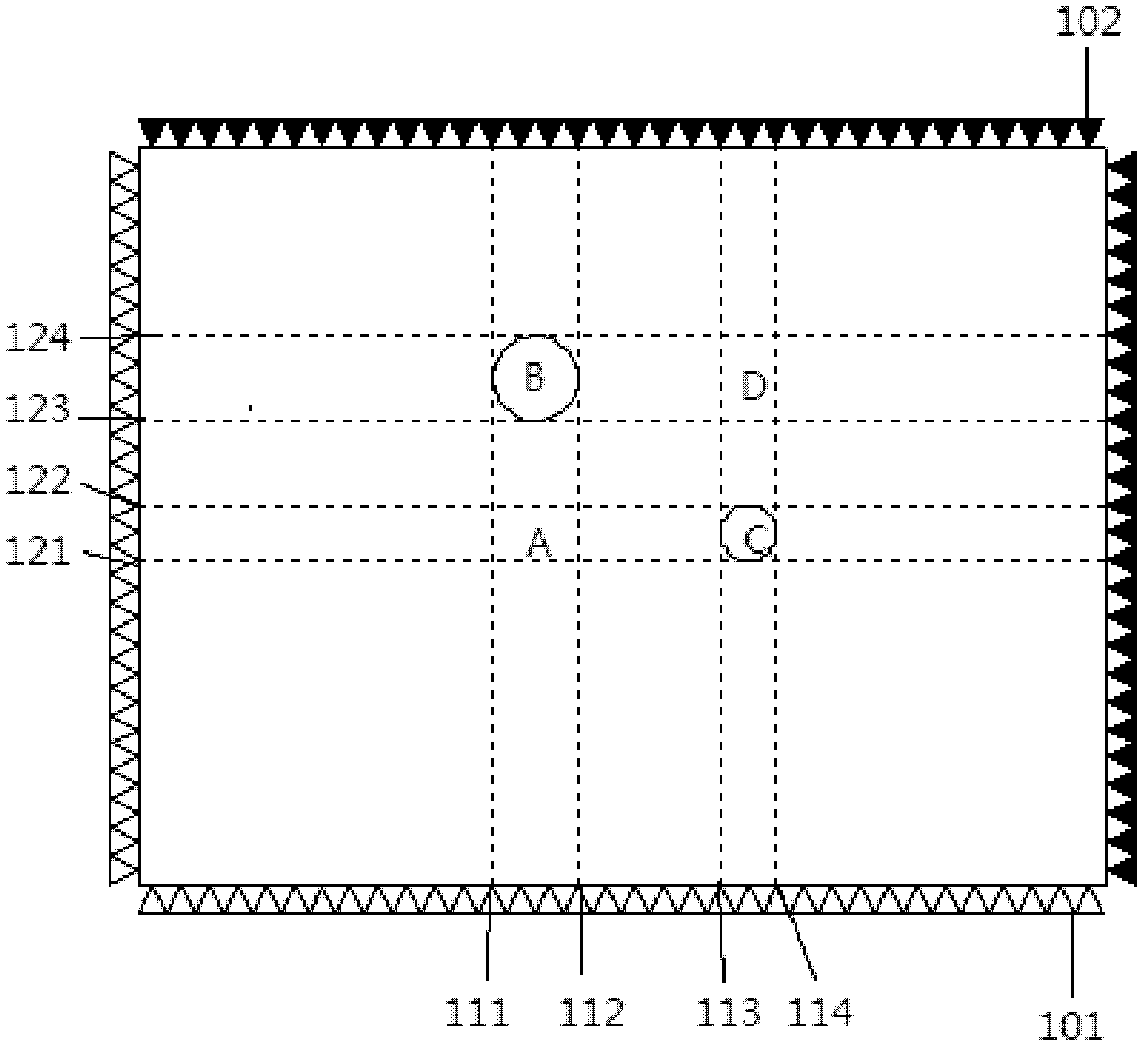
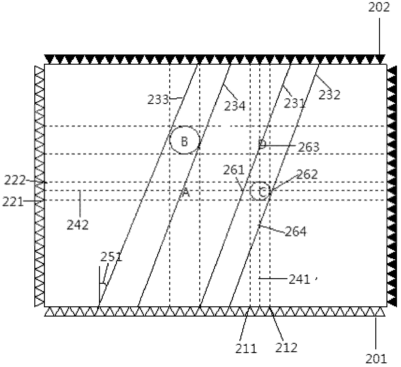
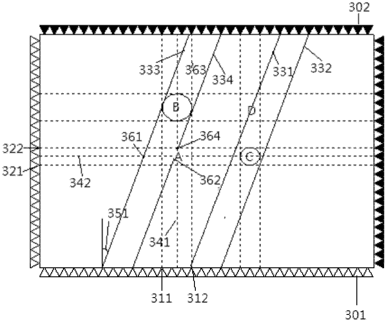
[0027] see first figure 1 and cooperate Image 6 shown, figure 1 In the middle 101 is a transmitting circuit board mounted with an infrared emitting element, and 102 is a receiving circuit board mounted with an infrared receiving element. 111, 112, 113, and 114 are logical data instances of touch information during X-axis scanning. 121, 122, 123, and 124 are logical data instances of touch information when the Y direct axis is scanned. 111 indicates the position of the starting point of a touch on the X axis, 112 indicates the position of the ending point of the touch; 113 is the position of the starting point of another touch on the X axis, and 114 is the position of the ending point of the touch. 121 indicates the position of the starting point of a touch on the Y axis, 122 indicates the position of the end point of the touch; 123 is the position of the starting po...


PUM


Abstract

The invention relates to a multi-point positioning method for an infrared matrix touch screen. The multi-point positioning method comprises the following steps of: S1, predetermining the number of axes to be scanned and corresponding angles; S2, scanning the axes of different angles in sequence, and generating logic data reflecting axis touch information after processing; S3, combining data intervals obtained in scanning of the X axis and the Y axis to obtain possible touch points; S4, calculating the intersection of the scanning area corresponding to the data interval in a single inclined scanning direction and one touch area generated by S3, and updating the long axis and the short axis in the touch area if the intersection exists; S5, repeating Step S4, calculating intersections of scanning areas corresponding to data intervals in other inclined axial directions and the touch point updated in Step S4, wherein the point does not exist when the intersections of the scanning areas corresponding to all the data intervals in one direction and the touch point updated in Step S4 is 0; otherwise, the point may be a real point; and S6, repeating Step S4 and S5, and calculating other possible touch areas in Step S3.

Description

technical field [0001] The invention relates to a method for detecting multiple touch points on an infrared matrix touch screen, in particular to a method for calculating the position and size of the multiple touch points. Background technique [0002] At present, the touch screen, as a humanized input device, has broad prospects for development. With the rapid development of the computer touch screen industry, the infrared touch screen has been widely used in various fields due to its simple production process, low production cost, convenient installation, maintenance-free, high explosion resistance, and high reliability. The basic structure of the infrared touch screen is to install several pairs of infrared emitting and infrared receiving elements in a certain order on the periphery of a suitable display surface. These transmitting and receiving elements form a transmitting and receiving pair according to a one-to-one correspondence, and form a mutually perpendicular tra...

Claims


Application Information

Patent Timeline
Patent Type & Authority Applications(China)
IPC IPC(8): G06F3/042
Inventor 张宇明徐姣
Owner SHANGHAI IRM TOUCH ELECTRONICS TECH
Learn More