Point-by-point correcting equipment and correcting method thereof for LED (Light-Emitting Diode) display screen in simulation field

A LED display, point-by-point correction technology, applied to static indicators, instruments, etc., can solve the problems of a large amount of manpower, material resources and time, low correction efficiency, low economic benefits, etc., to save travel expenses, high correction efficiency, Effect of Correction Difficulty Reduction

Inactive Publication Date: 2013-04-03
FUSHUN OPTOELECTRONICS TECH
View PDF8 Cites 4 Cited by
  • Summary
  • Abstract
  • Description
  • Claims
  • Application Information

AI Technical Summary

Problems solved by technology

Therefore, the current point-by-point calibration method of LED display screens has disadvantages such as inability to correct due to environmental reasons, low calibration

Method used


Image

  • Point-by-point correcting equipment and correcting method thereof for LED (Light-Emitting Diode) display screen in simulation field
  • Point-by-point correcting equipment and correcting method thereof for LED (Light-Emitting Diode) display screen in simulation field
  • Point-by-point correcting equipment and correcting method thereof for LED (Light-Emitting Diode) display screen in simulation field

Examples


Embodiment Construction

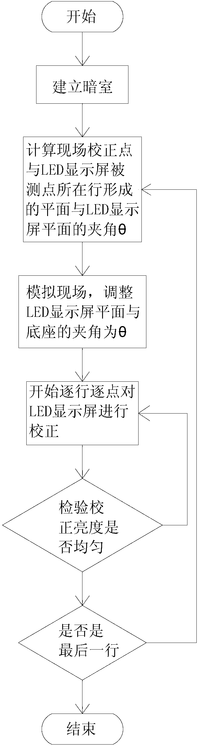
[0027] Below in conjunction with specific embodiment the present invention is described in further detail:

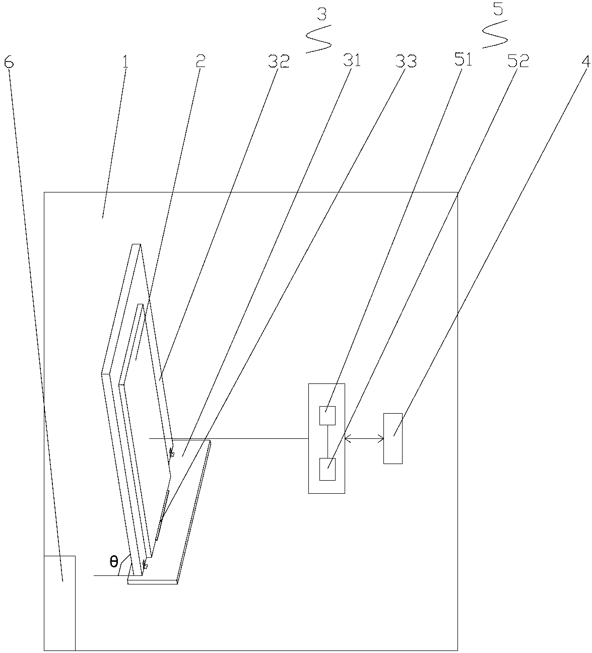
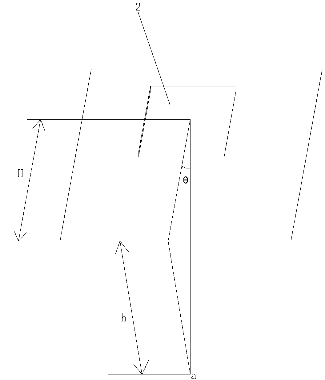
[0028] Such as figure 1 or figure 2 As shown, the present invention is a point-by-point correction device for LED display screens simulating the scene. The correction device includes a darkroom 1, and an LED display screen 2, a display screen correction frame 3, an LED control system 4 and a correction device installed in the dark room 1. The device 5 and the LED control system 4 are electrically connected to the LED display screen 2 and the calibration device 5 respectively. greater than 15m;

[0029] The display screen correction frame 3 includes a base 31 and a support plate 32, the bottom of the support plate 32 is rotationally connected with the base 31, the back of the LED display screen 2 is against the surface of the support plate 32, the bottom of the LED display screen 2 is placed on the base 31, and the LED display screen 2 is placed on the base 31. When ...


PUM

PropertyMeasurementUnit
Lengthaaaaaaaaaa

Abstract

The invention discloses point-by-point correcting equipment for LED (Light-Emitting Diode) display screen in a simulation field. The correcting equipment comprises a darkroom, and an LED display screen, a display screen correcting bracket, an LED control system and a correcting device which are arranged in the darkroom, wherein the central height of a measured line on the LED display screen is consistent with that of the correcting device; the display screen correcting bracket comprises a base and a support plate; the bottom of the support plate is connected with the base in a rotating manner; the back of the LED display screen leans against the surface of the support plate; the bottom of the LED display screen is arranged on the base; and when the LED display screen is corrected line by line and point by point, the included angle between the support plate and the base is adjusted to be theta. A point-by-point correcting method for the LED display screen is implemented in the darkroom without interference of environmental factors, the interference of adverse factors such as the environmental factors to correcting effects is eliminated, and the correcting difficulty is greatly reduced; and the angle between a plane formed on the line of a correcting point and a measured point on the plane of the LED display screen and a plane of the LED display screen is calculated in the simulation field, so that the correcting efficiency is higher.

Description

technical field [0001] The invention relates to a point-by-point correction technology for an LED display screen, in particular to a point-by-point correction device and a correction method for an LED display screen in a simulated scene. Background technique [0002] At present, LED chips have inconsistent brightness and wavelength during production, and the manufacturers of various LED displays have different production processes and production equipment, resulting in bright color differences and mosaics in full-color LED displays. The display effect of the LED display. Therefore, it is very necessary to correct the full-color LED display point by point, so as to improve the brightness and chromaticity uniformity of the LED display. [0003] The current point-by-point calibration of the LED display is mainly carried out at the installation site of the LED display. Generally, the light is dark at night, there is no obstruction in front of the LED display, the visibility is ...

Claims


Application Information

Patent Timeline
IPC IPC(8): G09G3/00G09G3/32
Inventor 陈阿军陈建顺姚进根杨佰成王宝良杨伟艺张真桂
Owner FUSHUN OPTOELECTRONICS TECH
Why Eureka
Try Eureka