Automatic transfer switching device with combined support

A technology of automatic transfer switch and combined bracket, which is applied in the direction of electric switches, circuits, electrical components, etc., can solve the problems of production, life impact, cumulative error, wrong opening and closing operation, etc., so as to avoid the problem of circuit breaker malfunction and reduce The number of transmission stages and the effect of reducing the cumulative error

Inactive Publication Date: 2013-04-03
SCHNEIDER WINGOAL TIANJIN ELECTRIC EQUIP
View PDF6 Cites 2 Cited by
  • Summary
  • Abstract
  • Description
  • Claims
  • Application Information

AI Technical Summary

Problems solved by technology

But there is following problem in this automatic transfer switch electrical appliance of this prior art: only be provided with motor support on this automatic transfer switch electrical appliance, motor 2 controls breaker 3 opening and closing by escapement 4, but, as mentioned above, motor 2 is installed on the motor bracket, the escapement 4 is installed on the mandrel 20, and the circuit breaker 3 is installed on the bottom plate 1. Since these transmission parts are installed on different parts, it may be caused by multi-stage The accumulative error in the position of the escapement 4 caused by transmission caused it to mistakenly touch the micro switch installed on the circuit breaker 3 to make it act. As a result, the micro switch sent an error signal to the controller, and finally the circuit breaker 3 Wrong opening and closing operations under the control of the controller will undoubtedly have a serious impact on normal production and life

Method used


Image

  • Automatic transfer switching device with combined support
  • Automatic transfer switching device with combined support
  • Automatic transfer switching device with combined support

Examples


Embodiment Construction

[0011] The automatic transfer switch appliance with combined bracket provided by the present invention will be described in detail below in conjunction with the accompanying drawings and specific embodiments. The same symbols are used for the same components as those in the prior art, and their descriptions are omitted.

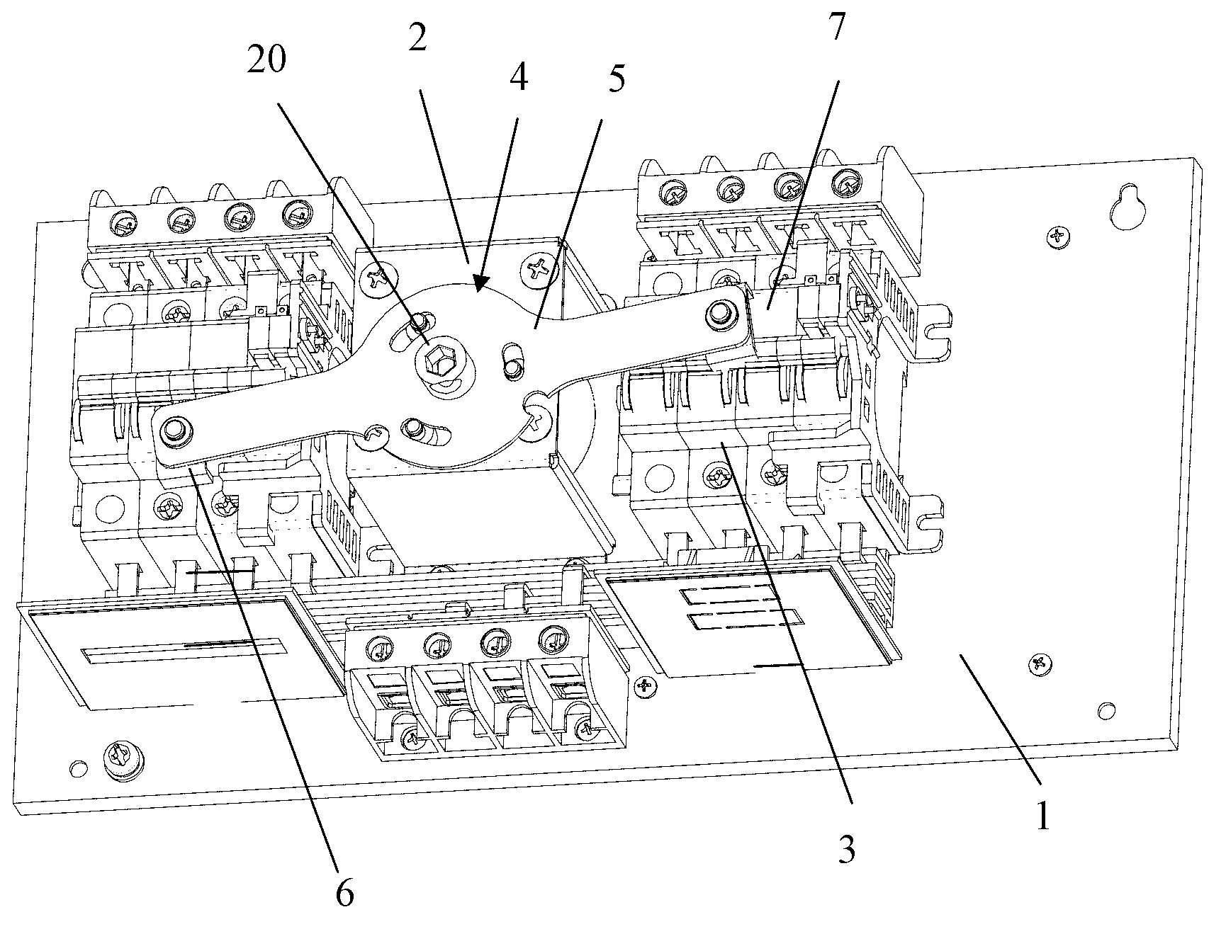
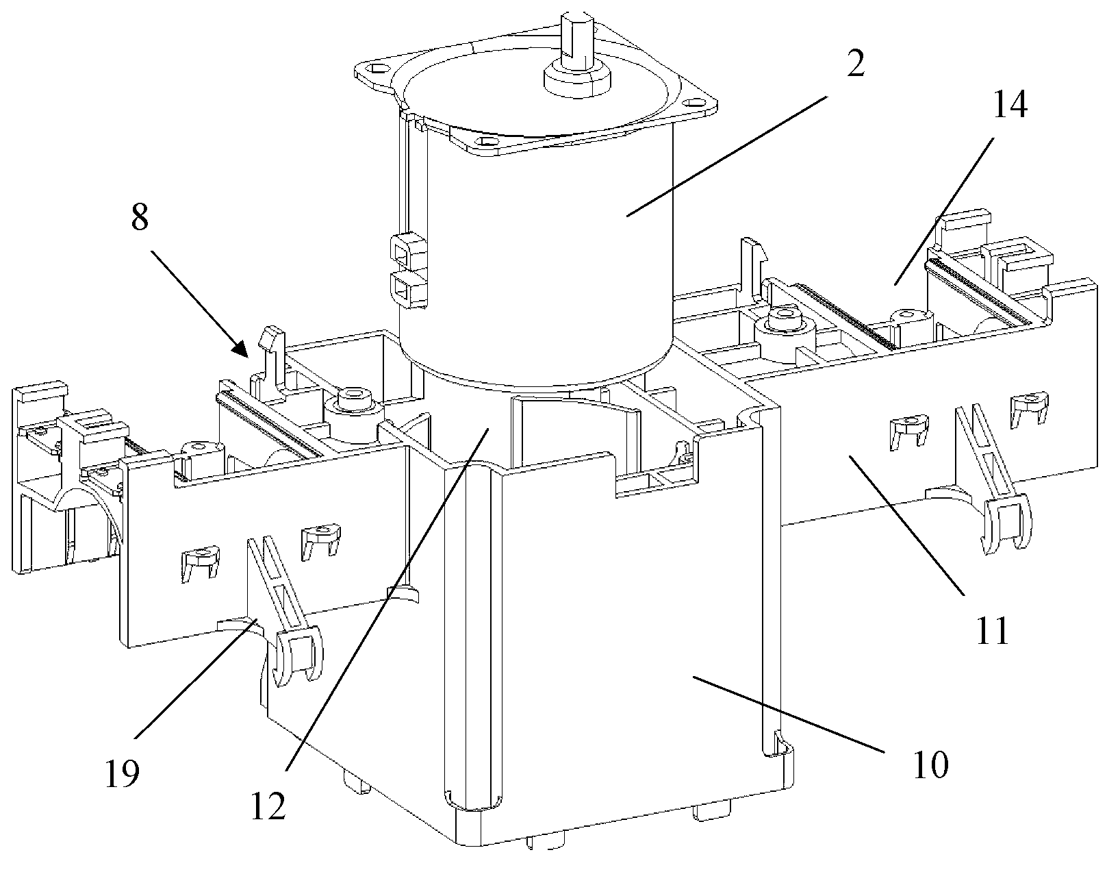
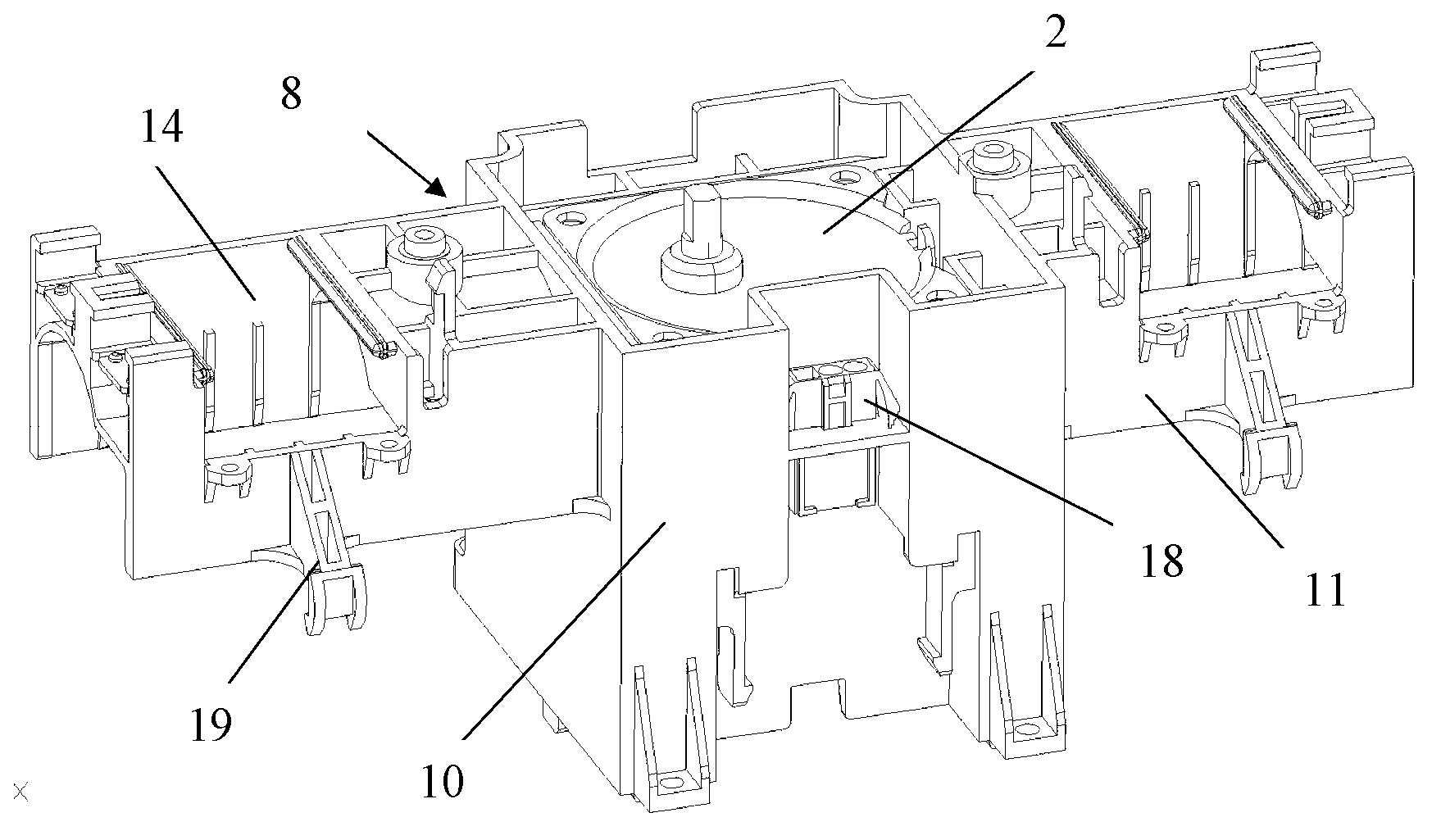
[0012] Such as Figure 2-Figure 5 and figure 1 As shown, the automatic transfer switch appliance with combined bracket provided by the present invention includes base plate 1, combined bracket, motor 2, two circuit breakers 3, mandrel 20, escapement 4, controller and casing not shown in the figure The combined bracket is installed on the surface of the base plate 1, and it is composed of a lower integral bracket 8 and a fixing part 9, wherein the lower integral bracket 8 is composed of a motor bracket 10 and two switch fixing brackets 11 that are respectively located on both sides of the motor bracket 10. Composition, the middle part of the motor bracket 10...


PUM


Abstract

An automatic transfer switching device with a combined support comprises a bottom plate, the combined support, a motor, two breakers, a mandrel, a release catch, a controller and a casing. The combined support is installed on the surface of the bottom plate and composed of a lower overall support and a fixed part, the lower overall support is formed by a motor support and two switch fixing supports located on two sides of the motor support integrally, the fixed part is installed at the upper end of the motor support, the motor is installed in a motor installation hole, the two breakers are arranged on the bottom plate surface located on two sides of the motor support, the release catch is installed on an output shaft of the motor, the controller is installed on one side of the bottom plate surface, and the casing is covered outside the combined support. The automatic transfer switching device enables the motor and the breakers to be fixed on the combined support, transmission stages of a transmission member can be reduced, accumulative error of the position of the transmission member because of multistage transmission in an operating process can be reduced so as to avoid malfunction of the breakers caused by the accumulative error, and normal production can be guaranteed.

Description

technical field [0001] The invention belongs to the technical field of electrical equipment, in particular to an automatic switch electrical appliance with a combined bracket. Background technique [0002] The automatic transfer switch appliance is a widely used terminal appliance. It mainly uses the controller on it to drive the electric operating mechanism to control the action of the switch, so as to connect or break the common and standby power supply, so as to ensure the safety and production of the power system. continuity. figure 1 It is a schematic diagram of the main components of a commonly used automatic transfer switch appliance. Such as figure 1 As shown, this automatic transfer switch appliance mainly includes a base plate 1, a motor 2, two circuit breakers 3, a mandrel 20, an escapement 4, a controller and a casing not shown in the figure; wherein the motor 2 is installed on the base plate 1 The middle part of the surface; two circuit breakers 3 are respect...

Claims


Application Information

Patent Timeline
Patent Type & Authority Applications(China)
IPC IPC(8): H01H9/02
CPCH01H2300/018
Inventor 岳鹏陈红群周慧刘津华陈程新张丰玺赵树兵
Owner SCHNEIDER WINGOAL TIANJIN ELECTRIC EQUIP
Why Eureka
Try Eureka