Reactive compensation device with variable capacitor module and variable capacitor module

A technology of variable capacitance and compensation device, applied in reactive power compensation, reactive power adjustment/elimination/compensation, multi-connected capacitors, etc., can solve the problems of poor compensation effect, low compensation efficiency, and too many compensation capacitors. , to achieve the effect of improving power supply efficiency and power consumption efficiency, high compensation efficiency, and reducing loss

Inactive Publication Date: 2013-04-03
ANHUI ONESKY POWER QUALITY TECH CO LTD
View PDF5 Cites 5 Cited by
  • Summary
  • Abstract
  • Description
  • Claims
  • Application Information

AI Technical Summary

Problems solved by technology

[0002] At present, the main application in the reactive power compensation market is TSC (Thyristor Swich Capacitor) thyristor switching compensation device. Cut, the disadvantage of this device is that it cannot be compensated continuously, the number of compensation capacitors is large, it is prone to overcompensation or undercompensation, the compensation effect is not good and the compensation efficiency is low
In addition, a SVG (Static Var Generator) static var compensation device has appeared on the market. The SVG reactive power compensation device uses power electronic technology to modulate the reactive power compensation amount to the grid. The disadvantage of the SVG reactive power compensation device is that the algorithm is complex , complex structure and high price

Method used


Image

  • Reactive compensation device with variable capacitor module and variable capacitor module
  • Reactive compensation device with variable capacitor module and variable capacitor module
  • Reactive compensation device with variable capacitor module and variable capacitor module

Examples


Embodiment Construction

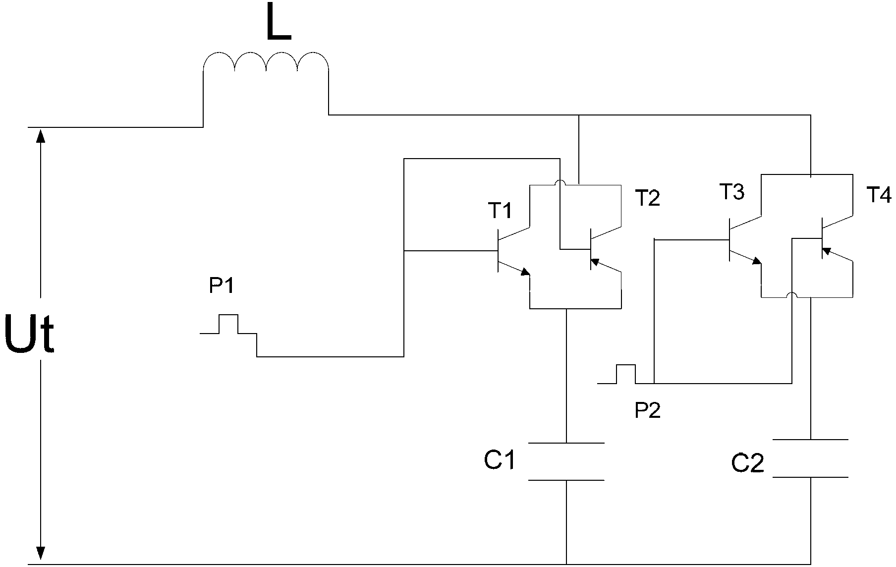
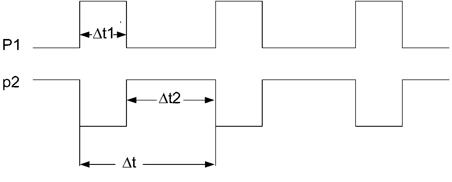
[0027] Combine below Figure 1~3 The working principle of the variable capacitor module will be described in detail first.

[0028] Such as figure 1 As shown, the variable capacitance module 30 includes two capacitance units connected in parallel with each other, and the two capacitance units are composed of a capacitance 31 connected in series with each other and a control switch 32; the capacitance 31 in the two capacitance units is grounded at one end, and the capacitance 31 The other end of the control switch 32 is connected to one end, and the control switch 32 is also provided with a control terminal for receiving a control signal to determine the on-off state of the control switch 32; the control switch 32 is composed of an NPN transistor and a PNP transistor , the emitter of the NPN transistor and the emitter of the PNP transistor are connected to each other and then connected in series with the capacitor 31, the collector of the NPN transistor and the collector of th...


PUM


Abstract

The invention belongs to the field of reactive compensation technologies and particularly relates to a reactive compensation device with a variable capacitor module and the variable capacitor module. The reactive compensation device comprises a control unit, a filter unit and the variable capacitor module. The variable capacitor module comprises two capacitor units connected with each other in parallel, each of the two capacitor units is composed of a capacitor and a regulation switch which are connected with each other in series, one ends of the capacitors of the two capacitor units are grounded, the other ends of the capacitors are connected with one ends of the regulation switches, the other end of the regulation switches are electrically connected with the filter unit, and a regulation end is further arranged in each regulation switch. An input end of the control unit is electrically connected with a bus, and an output end of the control unit is connected with regulation ends of the regulation switches. The filter unit is electrically connected with one phase of the three-phase bus. Continuous compensation can be achieved by the variable capacitor module, compensation efficiency is high, manufacturing cost is low, power supply efficiency and power utilization benefit of a power grid are increased effectively, and loss of the power grid is greatly reduced.

Description

technical field [0001] The invention belongs to the technical field of reactive power compensation, and in particular relates to a reactive power compensation device containing a variable capacitance module and the variable capacitance module thereof. Background technique [0002] At present, the main application in the reactive power compensation market is TSC (Thyristor Swich Capacitor) thyristor switching compensation device. Cut, the disadvantage of this device is that it cannot be compensated continuously, the number of compensation capacitors is large, it is prone to overcompensation or undercompensation, and the compensation effect is not good and the compensation efficiency is low. In addition, a SVG (Static Var Generator) static var compensation device has appeared on the market. The SVG reactive power compensation device uses power electronic technology to modulate the reactive power compensation amount to the grid. The disadvantage of the SVG reactive power compen...

Claims


Application Information

Patent Timeline
Patent Type & Authority Applications(China)
IPC IPC(8): H02J3/18H01G5/38
CPCY02E40/30
Inventor 李瑜张目
Owner ANHUI ONESKY POWER QUALITY TECH CO LTD
Why Eureka
Try Eureka