
Video equipment, display equipment and video system

A technology of video equipment and display equipment, applied in the field of video, can solve the problems of mixed signal lines, difficult identification, and limited distance, and achieve the effect of high data bandwidth, high data throughput, and flexible placement

Inactive Publication Date: 2013-04-03
KUANG CHI INST OF ADVANCED TECH +1
View PDF6 Cites 1 Cited by
  • Summary
  • Abstract
  • Description
  • Claims
  • Application Information

AI Technical Summary

Problems solved by technology

This connection method limits the placement of video equipment and display equipment and the distance between video equipment and display equipment, and it is easy to mix with other signal lines, making it difficult to identify

Method used


Image

  • Video equipment, display equipment and video system
  • Video equipment, display equipment and video system
  • Video equipment, display equipment and video system

Examples


Embodiment Construction

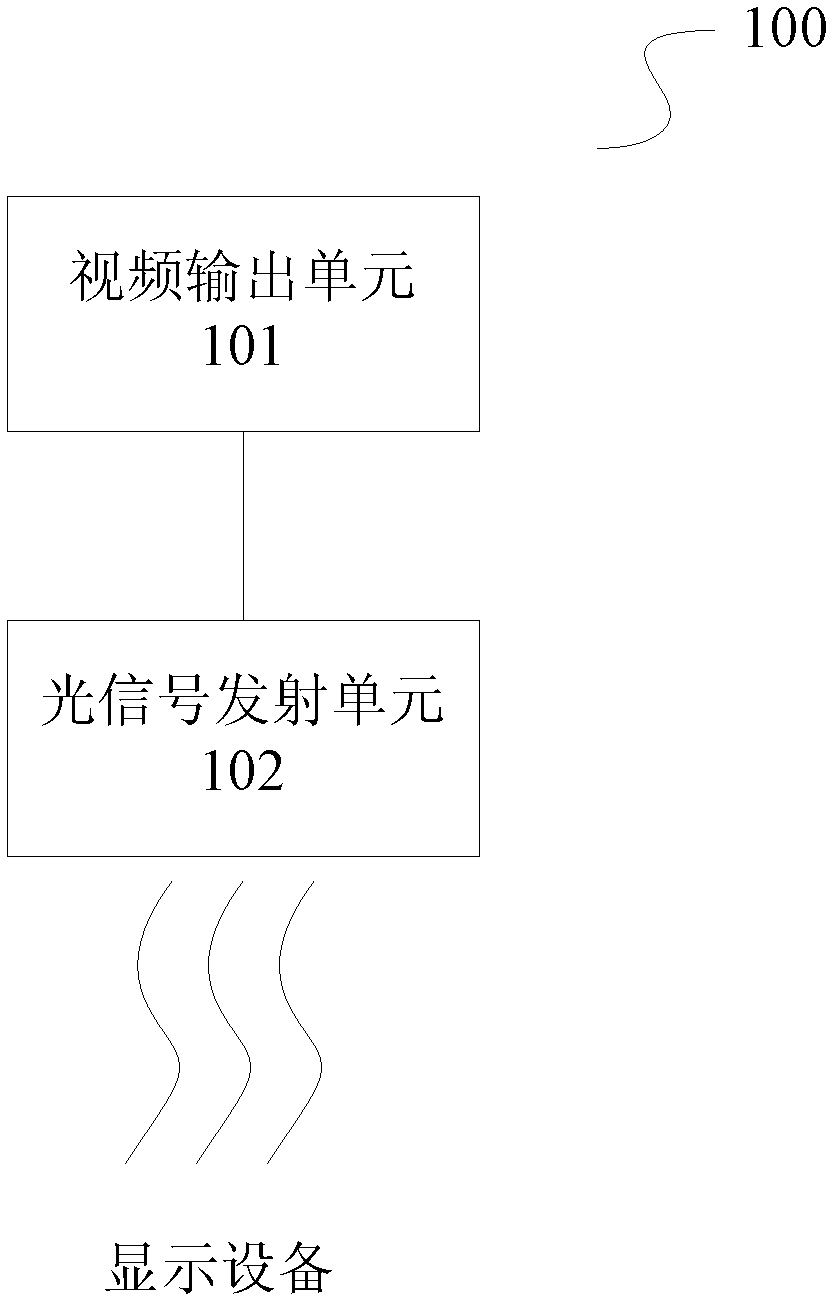
[0045] figure 1 is a schematic structural diagram of a video device according to an embodiment of the present invention. The video device 100 includes a video output unit 101 for outputting video signals, and an optical signal transmitting unit 102 .

[0046] An optical signal transmitting unit 102, configured to modulate the optical signal emitted by the optical signal transmitting unit 102 according to the video signal, so that the display device receives and demodulates the modulated optical signal, thereby restoring the video signal and displaying it .

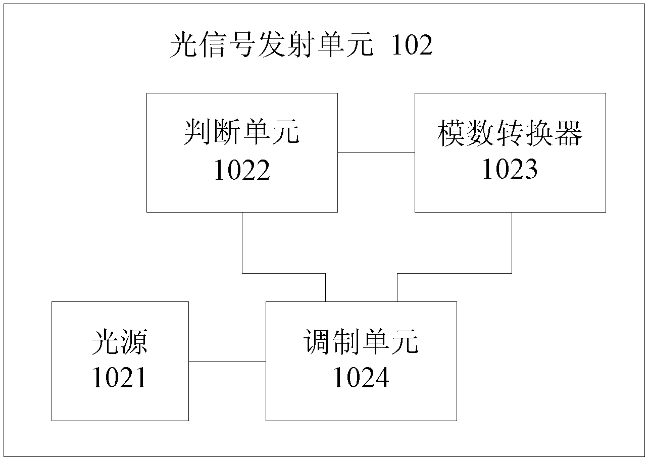
[0047] Wherein, the optical signal transmitting unit 102 includes a light source 1021, a judging unit 1022, an analog-to-digital converter 1023, and a modulating unit 1024, such as figure 2 shown. The judging unit 1022 is electrically connected to the analog-to-digital converter 1023 and the modulation unit 1024, the analog-to-digital converter 1023 is electrically connected to the modulation unit 1024, and the specifi...


PUM


Abstract

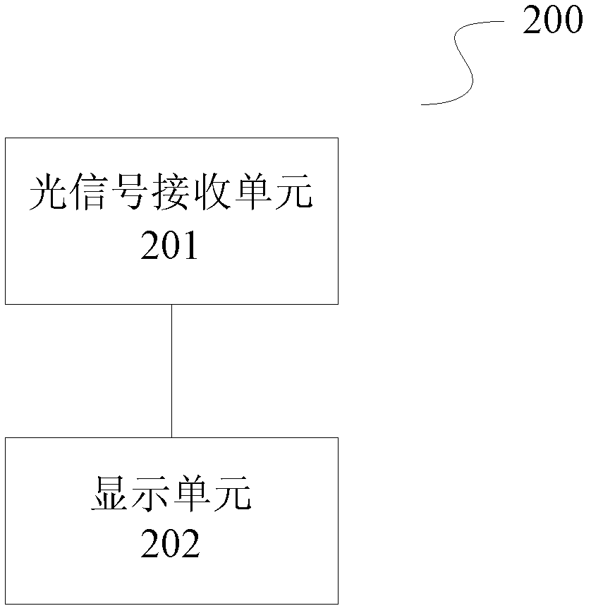
The invention relates to video equipment, display equipment and a video system. The video equipment comprises a video output unit and an optical signal emission unit, wherein the video output unit is used for outputting a video signal, the optical signal emission unit is used for modulating the optical signal emitted by the optical signal emission unit according to the video signal, so that the display equipment receives and demodulates the modulated optical signal, and the video signal is restored and displayed. The invention further provides the display equipment and the video system. According to the video equipment, the display equipment and the video system, a wired cable is not required to be used in the transmission process of the video signal, the condition of crossing and blending cables can be avoided, the video equipment and the display equipment can be more flexibly placed without the limit. In addition, the optical communication has a high data bandwidth range, thereby being applicable to high data throughout of the video signal.

Description

technical field [0001] The present invention relates to video technology, and more specifically, to video equipment, display equipment and video systems. Background technique [0002] Existing video devices (such as computer hosts, etc.) all need to be connected with a display device by wire to realize the transmission of video signals. This connection method limits the placement of the video device and the display device and the distance between the video device and the display device, and it is easy to be mixed with other signal lines, making it difficult to identify. Contents of the invention [0003] The technical problem to be solved by the present invention is to provide a video device, a display device and a video system that do not need to be connected by wired cables, aiming at the above-mentioned defects of the prior art that the placement position and placement distance are limited. [0004] The technical solution adopted by the present invention to solve its t...

Claims


Application Information

Patent Timeline
Patent Type & Authority Applications(China)
IPC IPC(8): H04N7/22
Inventor 刘若鹏栾琳刘京京刘豫青刘敏马伟涛李平军
Owner KUANG CHI INST OF ADVANCED TECH
Learn More