Method for detecting damage of bearing

A damage detection and bearing technology, applied to bearings, bearing assembly, bearing components, etc., can solve problems such as difficult characteristic frequencies

Inactive Publication Date: 2013-04-03
NIHON KENKI CO LTD
View PDF7 Cites 11 Cited by
  • Summary
  • Abstract
  • Description
  • Claims
  • Application Information

AI Technical Summary

Problems solved by technology

However, for actual bearings, slipping occurs between the inner ring, outer ring, and rolling elements, and it is difficult to theoretically obtain the eigenfrequency when slipping occurs

Method used


Image

  • Method for detecting damage of bearing
  • Method for detecting damage of bearing
  • Method for detecting damage of bearing

Examples


no. 1 approach

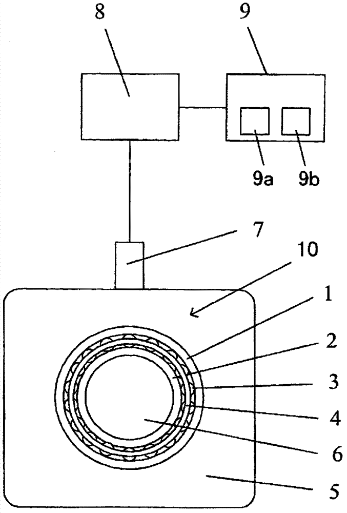
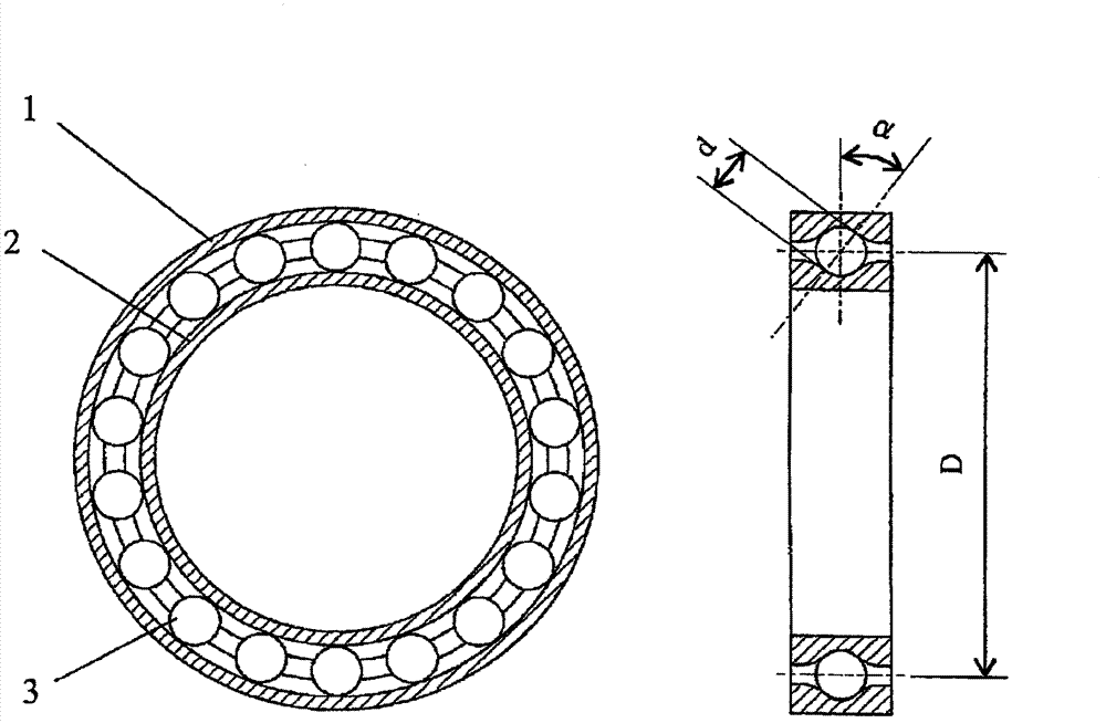
[0028] refer to Figure 1~4 A first embodiment of the bearing damage detection method of the present invention will be described. figure 1 It is a figure showing the structure of the bearing damage detection apparatus based on the bearing damage detection method of this invention, figure 2 It is a sectional view showing the structure of a single row deep groove ball bearing as an example of a radial ball bearing. The bearing damage detection device of this embodiment includes: an acceleration sensor 7 that measures vibration acceleration; an amplifier 8 that amplifies a signal output from the acceleration sensor 7 ; The bearing damage detection device according to this embodiment may be permanently installed on a device having a bearing to be detected for bearing damage, or may be a movable type device capable of detecting damage to bearings respectively installed on a plurality of devices. In the following description, a structure in which a bearing damage detection device...

no. 2 approach

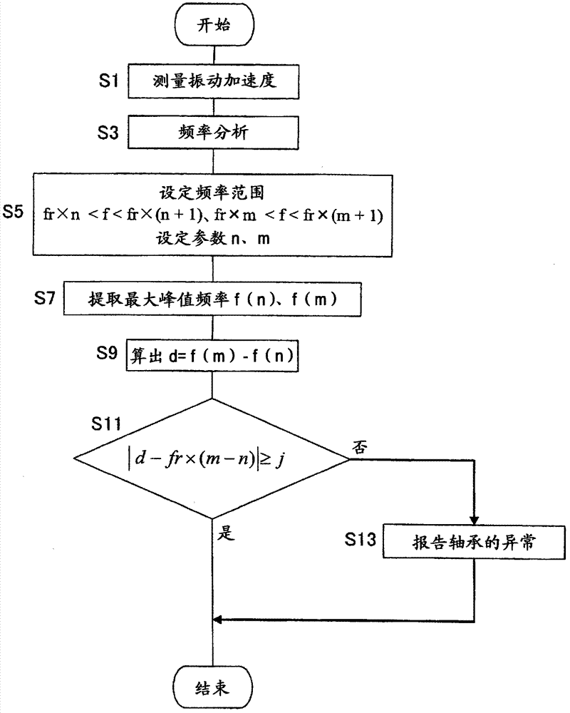
[0052] refer to Figure 5 , 6 A second embodiment of the bearing damage detection method according to the present invention will be described. In the following description, the same reference numerals are attached to the same components as those of the first embodiment, and differences will be mainly described. About the content which is not demonstrated especially, it is the same as 1st Embodiment. The present embodiment differs from the first embodiment mainly in the point of determining whether or not the bearing 10 is damaged based on the number of times described later.

[0053] Figure 5 It is a flowchart showing the processing content of the damage detection of the bearing in the second embodiment. In addition, in the following description, the processing content which detects whether the inner ring 2 is damaged or not is demonstrated as an example. After the unillustrated power switch of the bearing damage detection device is turned on and the start of the bearing...

no. 3 approach

[0070] refer to Figure 7 , 8 A third embodiment of the bearing damage detection method according to the present invention will be described. In the following description, the same reference numerals are assigned to the same components as those of the first and second embodiments, and differences will be mainly described. Points not particularly described are the same as those of the first or second embodiment. In the present embodiment, similar to the second embodiment, whether or not the bearing 10 is damaged is determined based on the order parameter g(u), but it differs from the first and second embodiments mainly in the following point: Whether or not the average value of the amplitude value of the maximum peak frequency f(u) within is changing with time is used to determine whether or not the damage of the bearing 10 is increasing.

[0071] Figure 7 It is a flowchart showing the processing content of the damage detection of the bearing in the third embodiment. In a...


PUM


Abstract

Disclosed is a method for detecting damage to a bearing which comprises an inner ring, an outer ring, a rolling body which rolls while being in contact with the inner ring and the outer ring, and a holder for holding the rolling body, wherein, vibration of the bearing is measured by a sensor while the movable side of the inner ring or the outer ring is rotating, a vibration waveform of the bearing obtained by the measurement by the sensor is subjected to frequency analysis, whether the bearing is damaged is determined on the basis of the result of the frequency analysis, wherein two or more frequency ranges are set so that the ranges do not overlap with each other and have ranges substantially equal to the rotation frequency (fr) of the movable side of the inner ring or the outer ring, peak frequencies are respectively obtained in the set plurality of frequency ranges, the difference between the obtained peak frequencies is compared with the value obtained by k-times the rotation frequency (fr) (k is an integer of 1 or more) to determine whether both compared values can be deemed as a match or not, and if both compared values are deemed to match, the bearing is judged as damaged.

Description

technical field [0001] The invention relates to a damage detection method of a bearing. Background technique [0002] A method of detecting damage to a bearing having an inner ring, an outer ring, rolling elements rolling in contact with the inner ring and the outer ring, and a cage holding the rolling elements is known. For example, a known method is to measure the vibration acceleration when the inner ring or the outer ring rotates, perform envelope processing on the obtained waveform, and perform frequency analysis to detect damage to the bearing based on the peak value of the characteristic frequency of the vibration caused by the damage ( Refer to Patent Document 1). [0003] prior art literature [0004] patent documents [0005] Patent Document 1: Japanese Patent Application Laid-Open No. 9-257651 [0006] In the method for detecting damage to a bearing described in the above-mentioned patent document, it is characterized in that not only the characteristic freque...

Claims


Application Information

Patent Timeline
Patent Type & Authority Applications(China)
IPC IPC(8): F16C19/52F16C41/00
CPCF16C19/52F16C19/527G06F17/00G01N29/14
Inventor 山本慎二郎
Owner NIHON KENKI CO LTD
Why Eureka
Try Eureka