Method for monitoring damage to a shaft

A damage and deformation technology, applied in the field of monitoring the damage of the shaft, can solve the problem of not directly detecting the damage of the shaft

Inactive Publication Date: 2015-01-07
SIEMENS AG
View PDF7 Cites 0 Cited by
  • Summary
  • Abstract
  • Description
  • Claims
  • Application Information

AI Technical Summary

Problems solved by technology

However, the current damage of th...

Method used


Image

  • Method for monitoring damage to a shaft
  • Method for monitoring damage to a shaft
  • Method for monitoring damage to a shaft

Examples


Embodiment Construction

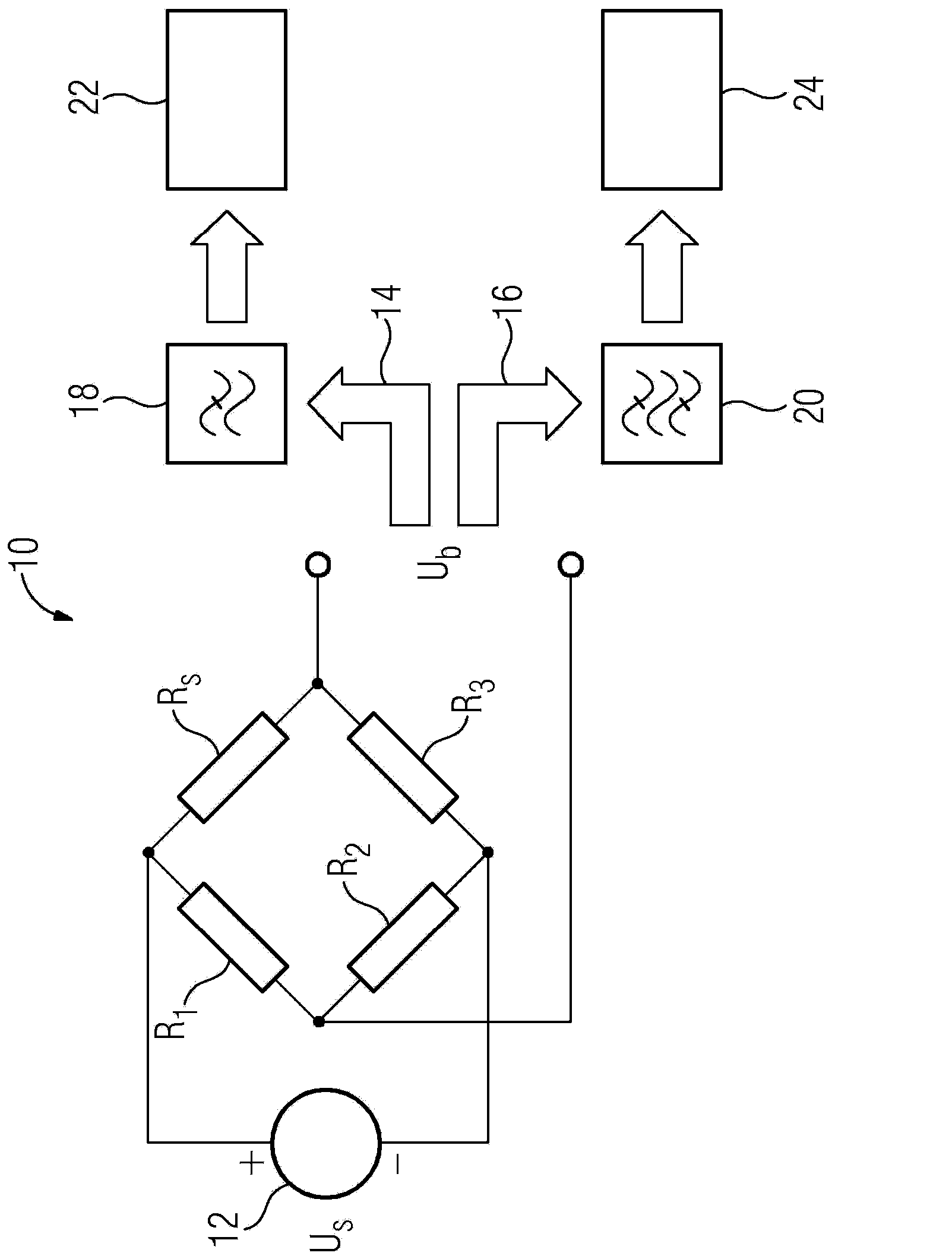
[0024] figure 1 A device 10 for monitoring damage to a shaft is shown. The device 10 includes a strain gauge R S , the strain gauge is shown here as a resistor. Strain gauge R S Together with the other three resistors R1, R2 and R3 are connected according to a Wheatstone bridge. The supply voltage U of the voltage supply system 12 S supplied to the bridge circuit. Strain gauge R S The measurement signal U b The bridge voltage, which can be used as a measuring bridge, is tapped.

[0025] Several strain gauges R can likewise be arranged on axes not shown here S . Strain gauge R S For example, it can be formed as a resistive wire on a foil. Strain gauge R S Can be made of metal or of semiconductor. Strain gauge R S It is preferably mounted on the outer surface of the shaft with a special adhesive. Because of the mechanical deformation of the shaft, the strain gauge R S mechanical deformation. Due to mechanical deformation the strain gauge R S resistance changes....


PUM


Abstract

The invention relates to a method for monitoring damage to a shaft by arranging at least one strain gauge (RS) on an outer surface of the shaft, detecting deformation of the shaft using a measurement signal (Ub) from the at least one strain gauge (RS) and detecting sound emissions of the shaft by evaluating the measurement signal (Ub) in the ultrasonic range.

Description

technical field [0001] The invention relates to a method for monitoring damage to a shaft. Furthermore, the invention relates to a device for monitoring damage to a shaft. Background technique [0002] Shafts are used to transmit force or torque and are commonly used in electric machines, transmissions and bearing arrangements. In order to avoid failure of these devices, the shafts are monitored for damage, which may be caused, for example, by mechanical stress on the shaft. In this way overloading of the shaft and thus a potential fracture of the shaft can be prevented. [0003] In order to be able to know the load on a shaft, the torque acting on the shaft is usually measured today. For this purpose, strain gauges are mounted or glued on the outer surface of the shaft. In this case, the energy supply and the measurement data of the rotating shaft are carried out either via contact rings or via telemeters. However, the current state of damage to the shaft is usually no...

Claims


Application Information

Patent Timeline
IPC IPC(8): G01M5/00
CPCG01M5/0083G01M13/00G01M5/0033G01M5/0066
Inventor 阿尔诺·哈施克汉斯-亨宁·克洛斯迪尔克·沙伊布纳于尔根·席默尔
Owner SIEMENS AG
Why Eureka
Try Eureka