Balanceable rotation element

A technology for rotating elements and elements, applied in the field of installing the rotating elements, can solve the problems of increasing the manufacturing cost of the motor, increasing the manufacturing cost of the rotor, etc.

Inactive Publication Date: 2013-04-03
ROBERT BOSCH GMBH
View PDF3 Cites 2 Cited by
  • Summary
  • Abstract
  • Description
  • Claims
  • Application Information

AI Technical Summary

Problems solved by technology

This balancing process must be performed individually for each rotor, which increases the manufacturing cost of the rotor and thus the motor

Method used


Image

  • Balanceable rotation element
  • Balanceable rotation element
  • Balanceable rotation element

Examples


Embodiment Construction

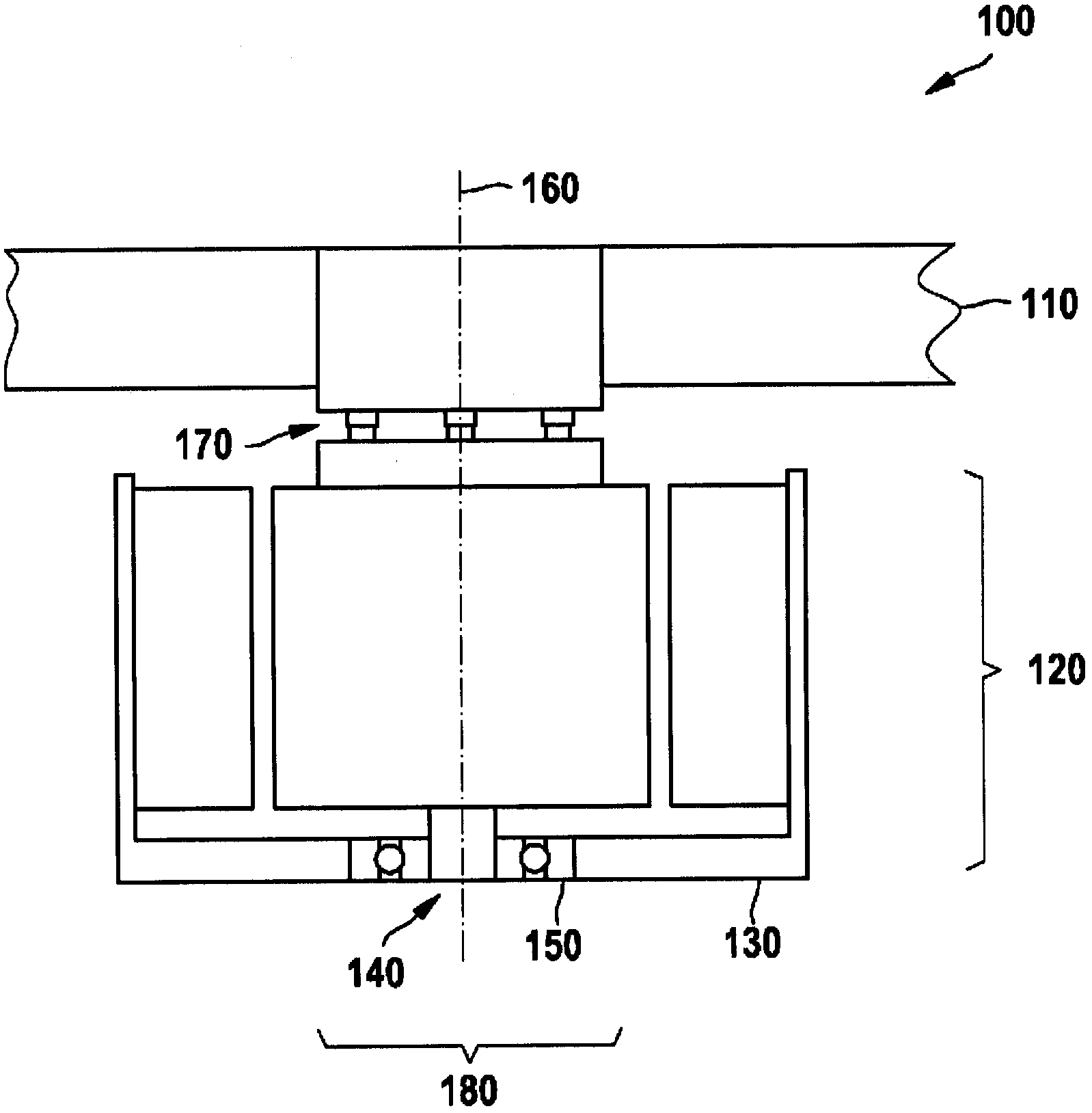
[0020] figure 1 A longitudinal section through an electric motor with a fan wheel is shown. The fan 100 includes a fan wheel 110 and a motor 120 . The electric motor 120 is formed of a stator (fixed member) 130 and a rotor (rotating member) 140 . Bearing 150 connects stator 130 and rotor 140 together such that rotor 140 is mounted rotatably relative to stator 130 about axis of rotation 160 . The fan wheel 110 is connected to the rotor 140 in a torque fit manner by means of a plurality of bearing elements 170 .

[0021] The fan 100 shown is only used as an exemplary embodiment for explaining the invention. The specific design of the fan 100 and in particular of the electric motor 120 should therefore not be included. For example, it is immaterial for the invention whether the electric motor 120 has permanent magnets and whether the permanent magnets are arranged on the stator 130 or on the rotor 140 . The fan wheel 110 is shown only in the region of the electric motor 120 ...


PUM


Abstract

A moving element is connected to a rotor of an electric motor in a manner locked in terms of torque and, together with the rotor, forms a rotation element. An angle of inclination of the moving element in relation to the rotor is defined by bearing elements which are arranged on a circumference about the axis of rotation of the rotor, wherein the bearing elements each define axial distances between the rotor and the moving element. Each bearing element is formed by a first and a second axial section, and the moving element can be brought into different rotational positions in relation to the rotor so as to produce different pairings of the first and second sections, said pairings corresponding to different angles of inclination.

Description

technical field [0001] The invention relates to a rotary element of an electric motor and a method for mounting the same. Background technique [0002] An electric motor includes a stator (fixed part) and a rotor (rotary part), which are rotatably supported relative to each other. The mass of the rotor may not be distributed exactly rotationally symmetrically, so that the rotor has a balance difference which may be static and / or dynamic. During operation of the electric motor, vibrations are generated by the balance difference, which can also be transmitted in the form of structure-borne sound and can lead to increased noise and vibration loads. In order to reduce the balance difference of the rotor, it is necessary to balance the rotor. Preferably, the rotor is balanced with a running element, which is connected to the rotor in a torque-fit manner and is intended to be driven by the electric motor. This balancing process has to be carried out individually for each rotor,...

Claims


Application Information

Patent Timeline
Patent Type & Authority Applications(China)
IPC IPC(8): H02K7/04
CPCH02K15/165H02K7/04F04D29/662
Inventor J·卡萨格兰德T·施奈德K·林嫩布罗克
Owner ROBERT BOSCH GMBH
Why Eureka
Try Eureka