A simple assembly and reusable balancing device and assembly method

The technology of a balancing device and an assembly method is applied to components of pumping devices for elastic fluids, non-variable pumps, pump components, etc., and can solve the problem that the balancing device cannot be used repeatedly, and the number of disassembly and assembly of fasteners is limited. Problems such as the influence of the rotor balance result, etc., achieve the effect of simplifying the rotor balancing process, saving the balancing cycle, and improving the efficiency of the rotor balancing

Active Publication Date: 2022-08-05
AECC SICHUAN GAS TURBINE RES INST
View PDF8 Cites 0 Cited by
  • Summary
  • Abstract
  • Description
  • Claims
  • Application Information

AI Technical Summary

Problems solved by technology

At the same time, the number of disassembly and assembly of fasteners is limited. When a certain number of disassembly and assembly is reached, new fasteners need to be replaced to ensure reliable connection of the rotor, resulting in greater waste
The existing balance device is composed of screws and locking pieces and the main body of the balance weight. During use, the locking piece needs to be deformed to lock the screws. The screws and the main body of the balance weight are connected by threads; when the balance device is disassembled, the lock The deformed shape and thread of the blade change, and the balance result of the rotor will be affected after the balance device is installed again, so the balance device cannot be used repeatedly

Method used


Image

  • A simple assembly and reusable balancing device and assembly method
  • A simple assembly and reusable balancing device and assembly method
  • A simple assembly and reusable balancing device and assembly method

Examples


Embodiment 1

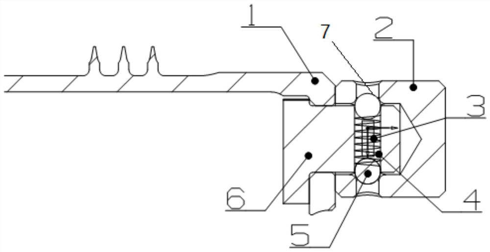
[0028] In this example, figure 1 Schematic diagram of the balancing device after assembly, such as figure 1 As shown, a simple assembly reusable balancing device is provided, the balancing device includes a rotor blisk 1 and a balancing weight assembly, the balancing weight assembly includes a balancing weight cap 2, a spring 3, a limiter 4, a ball I5 , ball II7 and balance block main body 6;

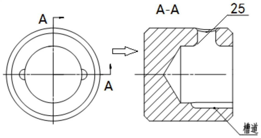
[0029] image 3 It is a schematic diagram of the structure of the balance block cap, such as image 3 As shown, the balance weight cap 2 is a cylindrical structure with countersunk holes, wherein the left figure is a top view, and the right figure is A-A cross-sectional view. The balancer cap 2 is provided with a first through hole, and a ball socket is provided at the intersection of the first through hole and the counterbore; the balancer cap 2 is provided with a groove perpendicular to the direction of the first through hole.

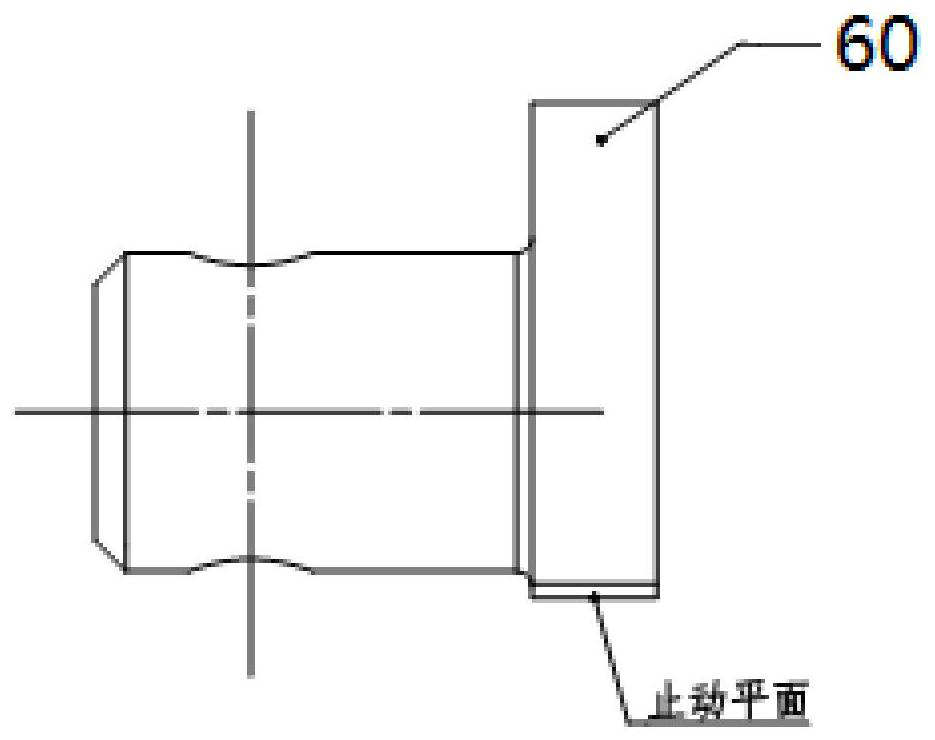
[0030] figure 2 It is a schematic diagram of the m...

Embodiment 2

[0036] This embodiment provides an assembly method of a rotor balancing device, using the above-mentioned balancing device, and the assembly method includes:

[0037] The fixed end of the balance weight body 6 passes through the installation through hole of the rotor blade disc 1, and the installation end of the balance weight body 6 is limited to one side of the rotor blade disc 1; the spring 3 is arranged in the second through hole, the ball I5, the ball II7 are located at both ends of the spring 3 and in the groove;

[0038] Rotate the balance weight cap 2, so that the ball I5 and the ball II7 roll from the groove to the ball socket 25, so that the spring 3 is in an extended state, so that the balance weight main body 6 and the balance weight cap 2 are connected.

[0039] Further, the stop plane on the mounting end of the balance weight body 6 is in contact with the rotor blisk 1 to prevent the balance weight body 6 from rotating when the rotor moves.

[0040] In this embo...


PUM


Abstract

The invention provides a simple assembly and reusable balancing device, the balancing device includes a rotor blisk (1) and a balancing weight assembly, the balancing weight assembly includes a balancing weight cap (2), a spring (3), a limiter (4), ball I (5), ball II (7) and balance weight body (6). In the invention, the rotor balance block is designed to be a non-threaded structure, and the assembly and disassembly of the balance block can be completed by simple tooling, thereby improving the assemblability of the rotor balance block.

Description

technical field [0001] The invention belongs to the field of aero-engine compressor design, in particular to a simple-assembled and reusable balancing device. Background technique [0002] The core engine is a vital core component of an aero-engine, and it is in the "three-high" (high temperature, high pressure, high speed) working environment, and its working state will have a huge impact on the entire engine. The stable operation of the rotor of the core engine is the basic guarantee for the safe operation of the engine. The introduction of engine rotor imbalance is the main cause of rotor vibration. [0003] There are various means of rotor balancing, such as the removal of excess material, or the addition of balance weights and so on. [0004] During the actual use of the engine, under the influence of the use state, the balance state of the engine rotor continues to deteriorate, requiring regular maintenance and re-balancing the rotor, resulting in the rotor needing t...

Claims


Application Information

Patent Timeline
Patent Type & Authority Patents(China)
IPC IPC(8): F04D29/66F04D29/26
CPCF04D29/662F04D29/26
Inventor 陈晓文陈佳钟明桥赵亮亮
Owner AECC SICHUAN GAS TURBINE RES INST
Why Eureka
Try Eureka