Control method and system for voltage balance of battery system

A battery system and voltage equalization technology, applied in charge equalization circuit, battery circuit device, arrangement of multiple synchronous batteries, etc., can solve problems such as unsatisfactory effect of voltage difference in battery clusters

Pending Publication Date: 2019-12-13
SHANGHAI ELECTRICAL GUOXUAN NEW ENERGY TECH CO LTD
View PDF6 Cites 7 Cited by
  • Summary
  • Abstract
  • Description
  • Claims
  • Application Information

AI Technical Summary

Problems solved by technology

[0006] The technical problem to be solved by the present invention is to provide a control method and system for voltage equalization of the battery system in order to overcome the defect in the prior art that the voltage difference equalization effect of the battery cluster in the battery system is not ideal

Method used


Image

  • Control method and system for voltage balance of battery system
  • Control method and system for voltage balance of battery system
  • Control method and system for voltage balance of battery system

Examples


Embodiment 1

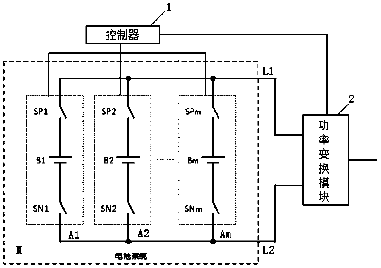
[0123] The battery system of this embodiment includes at least two battery clusters.

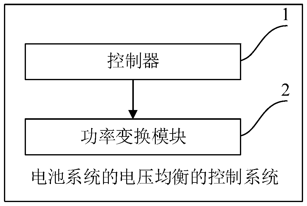
[0124] like figure 1 As shown, the voltage equalization control system of the battery system in this embodiment includes a controller 1 and a power conversion module 2 .

[0125] The controller 1 is electrically connected to each battery cluster, and the power conversion module 2 is electrically connected to the controller 1 and each battery cluster.

[0126] The controller 1 is used to collect the voltage value of each battery cluster.

[0127] The controller 1 is also used to judge whether the battery system satisfies the preset equalization condition according to the voltage value, and if so, determine the target battery cluster in the battery system that needs voltage equalization, generate a control command and send it to the power conversion module 2;

[0128] The power conversion module 2 is used to perform voltage equalization control (that is, charge or discharge) on the target ba...

Embodiment 2

[0133] The voltage balance control system of the battery system in this embodiment is a further improvement on Embodiment 1, specifically:

[0134] Each battery cluster includes a battery pack and a switch unit.

[0135] The battery pack is electrically connected to the switch unit, and the controller is electrically connected to the switch unit;

[0136] The controller is used to control the closing and opening of the switch unit;

[0137] The switch unit is used to control the corresponding battery pack to be in a power-on state or a power-off state.

[0138] Preferably, the switch unit includes a positive contactor and a negative contactor.

[0139] One end of the positive pole contactor is electrically connected to the positive pole bus bar, the other end of the positive pole contactor is electrically connected to the positive pole of the battery pack, the negative pole of the battery pack is electrically connected to one end of the negative pole contactor, and the other...

Embodiment 3

[0226] The method for controlling the voltage balance of the battery system in this embodiment is implemented by using the control system for the voltage balance of the battery system in Embodiment 1 or 2.

[0227] like Figure 4 As shown, the voltage equalization control system of the battery system in this embodiment includes:

[0228] S101. The controller collects the voltage value of each battery cluster;

[0229] S102. The controller judges whether the battery system satisfies the preset balance condition according to the voltage value, and if so, executes step S103;

[0230] Specifically, the controller sorts the voltage values ​​of each battery cluster, obtains the highest voltage value and the lowest voltage value among the voltage values, and calculates the difference between them;

[0231] The preset equalization condition includes that the difference is greater than a first set threshold.

[0232] S103. Determine the target battery cluster that needs voltage equa...


PUM


Abstract

The invention discloses a control method and system for voltage balance of a battery system. The battery system comprises at least two battery clusters, and the control system comprises a controller.The controller is used for collecting the voltage value of each battery cluster. The controller is also used for judging whether the battery system meets a preset balance condition or not according tothe voltage values. If the battery system meets the preset balance condition, the controller determines a target battery cluster needing voltage balance in the battery system according to the voltagevalues and performs voltage balance control on the target battery cluster. According to the invention, voltage balance among all the battery clusters can be actively completed, and the balance efficiency is improved; no extra energy loss is caused, and the influence on the service life and safety of the battery clusters is avoided; and in addition, additional devices do not need to be added, andthe cost is low.

Description

technical field [0001] The invention relates to the technical field of electric energy storage, in particular to a method and system for controlling voltage balance of a battery system. Background technique [0002] Batteries have been widely used in the field of electric energy storage, such as electric vehicles, energy storage, etc. In actual use, a large number of single batteries are connected in parallel and in series to form a battery system to meet energy and capacity requirements. In a typical energy storage application, multiple single cells are connected in parallel and series to form a battery pack, and multiple battery packs are connected in series to form a battery cluster. Therefore, the voltage of the battery cluster is relatively high, generally 500V to 900V. [0003] Since the internal resistance of the single battery is small, the battery cluster is composed of a plurality of single batteries passing through low-impedance conductive metal, so the internal r...

Claims


Application Information

Patent Timeline
Patent Type & Authority Applications(China)
IPC IPC(8): H02J7/00
CPCH02J7/0016H02J7/0019
Inventor 张俊孙越陈谦叶飞李霄李杨
Owner SHANGHAI ELECTRICAL GUOXUAN NEW ENERGY TECH CO LTD
Why Eureka
Try Eureka