
Robot system and method for producing a to-be-processed material

A technology of robot system and processed object, which is applied in the direction of manufacturing tools, general control system, control/regulation system, etc., and can solve the problems of laser blurring and whitening

Inactive Publication Date: 2013-04-10
YASKAWA DENKI KK
View PDF8 Cites 7 Cited by
  • Summary
  • Abstract
  • Description
  • Claims
  • Application Information

AI Technical Summary

Problems solved by technology

[0005] However, in the robot system described in the above-mentioned Patent Document 1, a plurality of workpieces are arranged inside a box-shaped stocker having a flat side surface and a bottom surface. The flat side and bottom reflect the laser light, and the image of the part where the reflected laser light is particularly strong may appear blurred or whitish (halation).

Method used


Image

  • Robot system and method for producing a to-be-processed material
  • Robot system and method for producing a to-be-processed material
  • Robot system and method for producing a to-be-processed material

Examples


Embodiment Construction

[0046] Embodiments of the present invention will be described below based on the drawings.

[0047] First, refer to Figure 1 to Figure 9 The configuration of the robot system 100 of this embodiment will be described.

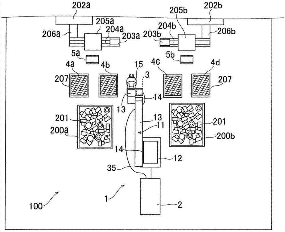
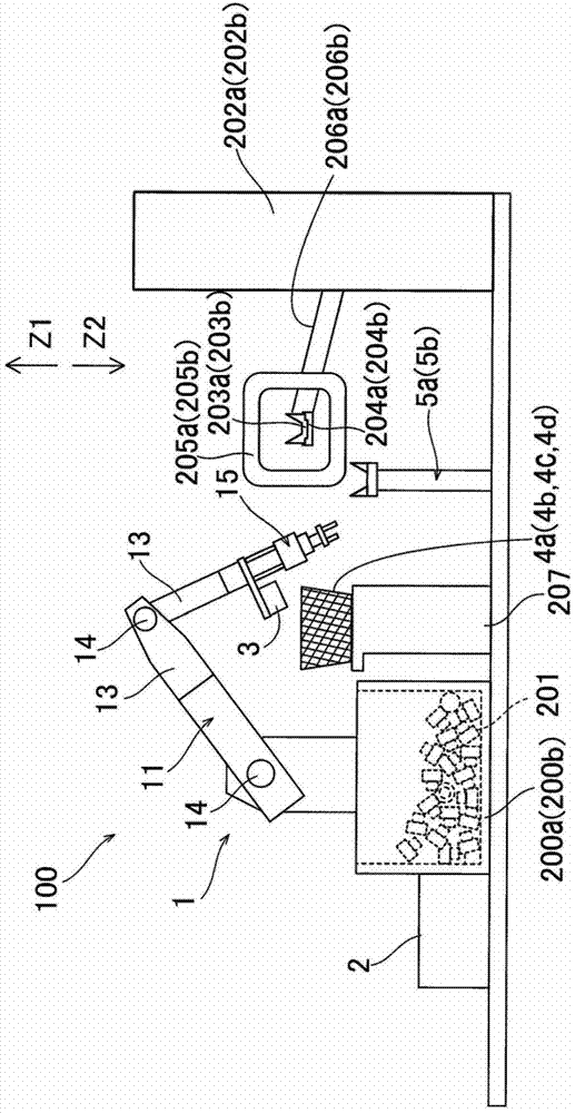
[0048] Such as figure 1 As shown, the robot system 100 has: a robot 1; a robot controller 2, which is used to control all actions of the robot system 100; a configuration state detection part 3; four temporary placement parts 4a, 4b, 4c and 4d, which are used for the Temporary placement; and changing stations 5a and 5b, which are used to change the workpiece 201. Also, two workpiece pallets 200 a and 200 b having a plurality of workpieces 201 arranged therein are arranged adjacent to the robot system 100 . Moreover, two of the four temporary storage parts 4a, 4b, 4c, and 4d are respectively arranged with respect to each workpiece pallet 200a, 200b. In addition, the robot controller 2 is an example of the "control part" of this invention. Moreover, the temp...


PUM


Abstract

The present invention provides a robot system and a method for producing a to-be-processed material, capable of suppressing halo (dim) when detecting a configuration state of a maintained object. The robot system (100) includes: a container (4a,4b,4c,4d), formed into a reticulated shape and configured to accommodate a plurality of workpieces (201); a configuration state detector (3), configured to detect configuration states of the plurality of respective workpieces (201) disposed in the container (4a,4b,4c,4d); and a robot arm (11) including a holder (15) configured to hold the workpiece (201) based on the configuration states of the plurality of workpieces (201) detected by the configuration state detector (3).

Description

technical field [0001] The present invention relates to a robot system and a method of manufacturing a workpiece, and more particularly, to a robot system and a method of manufacturing a workpiece having a robot arm including a holding portion for holding an object to be held. Background technique [0002] Conventionally, a robot system having a robot arm including a holding unit for holding an object is known (for example, refer to Patent Document 1). [0003] The robot system disclosed in the aforementioned Patent Document 1 includes: a robot arm having a gripping device (holding unit) for holding a workpiece (holding object); A plurality of workpieces are inspected (photographed), and the stocker has flat side and bottom surfaces. In the robot system of Patent Document 1 described above, the arrangement states of the plurality of workpieces are detected by imaging the plurality of workpieces arranged inside the stocker with the sensor unit. After that, the robot arm is ...

Claims


Application Information

Patent Timeline
IPC IPC(8): B25J9/16B25J13/08
CPCG05B2219/40613G05B2219/39508G05B2219/39567G05B2219/45063G05B2219/40014B25J9/1687G05B2219/40053B25J9/1697Y02P80/40
Inventor 安田裕也福岛和彦
Owner YASKAWA DENKI KK
Learn More