Cable box

A cable box, dust technology, applied in the direction of engine components, machines/engines, casings, etc., can solve problems such as oil leakage that can no longer be reliably prevented, and achieve the effects of preventing dust intrusion, suppressing manufacturing costs, and suppressing increase

Active Publication Date: 2013-04-10
MITSUBISHI MOTORS CORP
View PDF7 Cites 0 Cited by
  • Summary
  • Abstract
  • Description
  • Claims
  • Application Information

AI Technical Summary

Problems solved by technology

However, when the dust entrained by the rotation of the crankshaft pulley is deposited in the above-mentioned gap, or when

Method used


Image

  • Cable box
  • Cable box
  • Cable box

Examples


Embodiment Construction

[0045] Hereinafter, embodiments of the present invention will be described in detail based on the drawings.

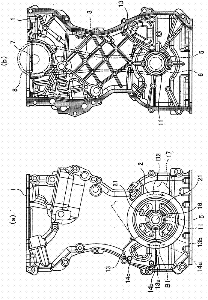
[0046] Such as figure 1 As shown in (a), the crank pulley 2 is provided on the surface side of the chain case 1, and on the other hand, as shown in figure 1 As shown in (b), the endless chain 3 is provided on the back side of the chain case 1 .

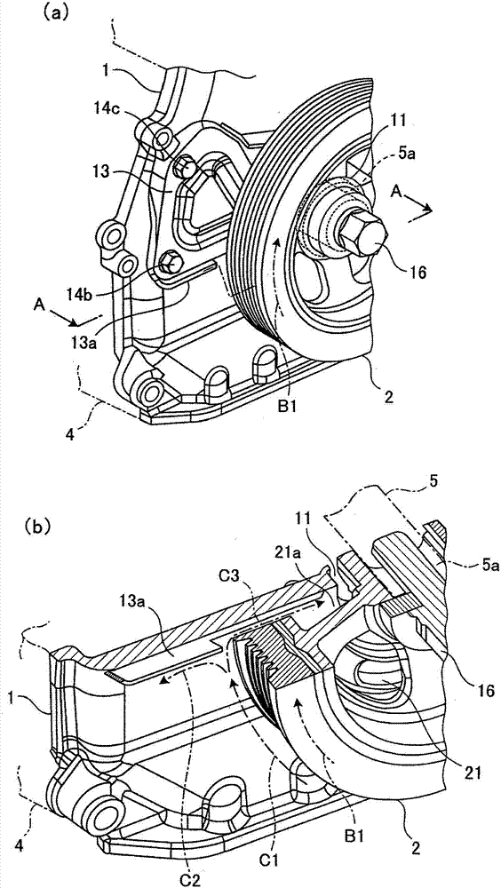
[0047] Such as figure 1 As shown in (b), the chain 3 is respectively wound on the sprocket 6 and the sprocket 8, wherein the sprocket 6 is fixed on the engine 4 (refer to image 3 ) on the crankshaft 5 at the lower part (cylinder block side), the sprocket 8 is fixed on the engine 4 (refer to image 3 ) on the upper (cylinder head side) camshaft 7, and transmits the rotational force of the crankshaft 6 to the camshaft 8. Such as image 3 As shown, the chain case 1 is fixed to the side of the engine (cylinder head and cylinder block) 4 by bolts (not shown), thereby covering the chain 3 .

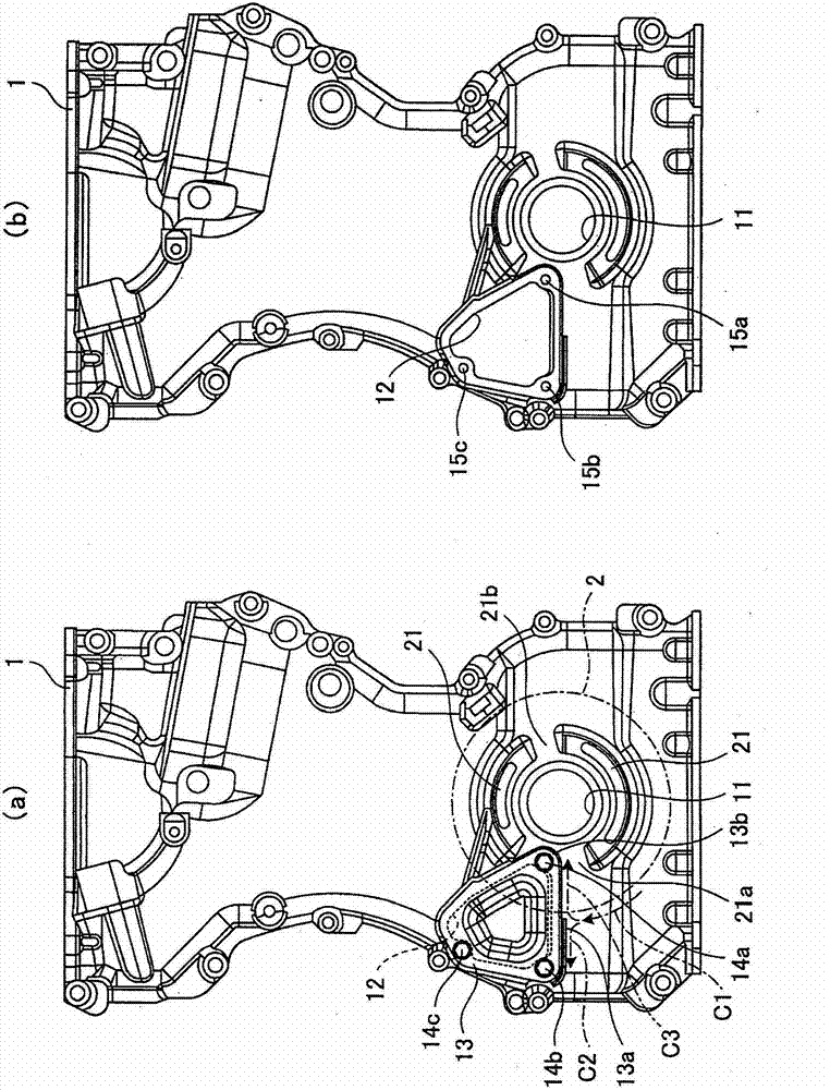
[0048] Such as figure 2 (a), ...


PUM


Abstract

The invention relates to a cable box which is a chain box having a structure preventing dust invasion. The chain box (1) is fixed on the side surface of the engine to cover the circular chain transmitting the rotating force of a crankshaft to a camshaft, and the surface side is provided with a crankshaft belt wheel (2) fixed at the end of the crankshaft inserted in the crankshaft hole (11), and a dust invasion proofing part (the lower end of a maintenance cover (13),a return part (13a), and a bolt (14a)) which is opposite to the rotating direction of the crankshaft belt wheel (2) and prevents dust from invading from the crankshaft hole (11) to the chain box (1) is arranged between the surface sides of the crankshaft belt wheel (2) and a chain box (1). Furthermore, a part (13b) of the maintenance cover (13) and the bolt (14a) are arranged at the incision (21a) of the edge (21) for preventing dust invasion.

Description

technical field [0001] The invention relates to a cable box such as a chain box. Background technique [0002] The chain case is fixed to the side of the vehicle's engine (cylinder head and cylinder block) to cover the endless chain that transmits the rotational force of the crankshaft to the camshaft. On the other hand, a crank pulley is provided on the surface side of the chain case. The crankshaft pulley is fixed to the end of the crankshaft inserted through the crankshaft hole. The crankshaft pulley is surrounded by an auxiliary machine belt, and the rotational force of the crankshaft is transmitted to auxiliary machines such as an alternator or an air conditioner compressor by means of the auxiliary machine belt. [0003] Specifically, the above-mentioned crankshaft is inserted into the oil seal, and when the rotation of the crankshaft is stopped, the pressing force of the oil seal is used, and when the crankshaft rotates, air is sucked into the engine from a small ga...

Claims


Application Information

Patent Timeline
IPC IPC(8): F02F7/00
Inventor 成田敏夫伊东庆忠酒井知治宫原宏享野村幸弘
Owner MITSUBISHI MOTORS CORP
Why Eureka
Try Eureka