Transmission for wheeled machine

a technology of transmission system and wheeled machine, which is applied in the direction of clutches, freewheel clutches, agriculture tools and machines, etc., can solve the problems of high roll-back friction that the user must overcome, high load on the design, and high customer complaints

Active Publication Date: 2019-10-03
HONDA MOTOR CO LTD
View PDF0 Cites 1 Cited by
  • Summary
  • Abstract
  • Description
  • Claims
  • Application Information

AI Technical Summary

Benefits of technology

[0003]According to one aspect, a transmission for a manually operated wheeled machine having a drive condition and a freewheeling condition is provided. The transmission comprises an output shaft having a close-ended channel formed in an end portion thereof. The channel extends in an axially longitudinal direction of the output shaft and is axially spaced from an end face of the output shaft. A drive gear is rotatably mounted on the end portion of the output shaft. The drive gear includes an engaging groove formed in an inner peripheral surface of the drive gear. The drive gear is meshingly engaged with a driven gear carried within a drive wheel of the wheeled machine. A ratchet has a key portion and a leg portion extending from the key portion in a radial direction of the output shaft. The key portion is received in the channel and is in selective engagement with the engaging groove. A holder is rotatably mounted on the end portion of the output shaft. The holder includes an end face confronting the drive gear. A relief formed in the end face receives the leg portion of the ratchet. A friction member is secured to the holder and adapted to apply radial friction to the holder to temporarily prevent rotation of the holder with the output shaft in the drive condition of the wheeled machine. As a result, the key portion of the ratchet is moved into engagement with the engaging groove of the drive gear, and in the drive condition the output shaft rotates in a first rotational direction together with the drive gear and the holder. In the freewheeling condition the output shaft is stationary, and an overdrive of the drive gear in the first rotational direction results in disengagement of the key portion of the ratchet with the engaging groove allowing for free rotation of the drive gear about the stationary output shaft.
[0004]According to another aspect, a manually operated wheeled machine has a drive condition and a freewheeling condition. The wheeled machine comprises a motor and an output shaft operably coupled to the motor. The output shaft has a close-ended channel formed in an end portion thereof. The channel extends in an axially longitudinal direction of the output shaft and is axially spaced from an end face of the output shaft. A drive wheel is connected to the end portion of the output shaft. The drive wheel includes an inside wheel cover having an opening for the output shaft. A transmission is housed within the drive wheel. The transmission includes a drive gear rotatably mounted on the end portion of the output shaft. The drive gear includes an engaging groove formed in an inner peripheral surface of the drive gear. A ratchet has a key portion and a leg portion. The key portion is received in the channel. The ratchet is in selective engagement with the engaging groove of the drive gear. A holder is rotatably mounted on the end portion of the output shaft immediately adjacent the drive gear. The holder includes an end face having a relief formed therein which receives the leg portion of the ratchet. A driven gear carried within the drive wheel is meshingly engaged with the drive gear. To prevent dust intrusion into the channel the drive gear and the holder are arranged on the end portion of the output shaft to cover the channel, and the inside wheel cover includes a shroud covering each of the drive gear and the holder.

Problems solved by technology

This causes high roll-back friction that the user must overcome to move the lawnmower backwards.
In many cases, the pullback load is high enough to cause customers to complain about high load.
However, this design is susceptible to dust intrusion because of tight tolerances of the mating parts.

Method used


Image

  • Transmission for wheeled machine
  • Transmission for wheeled machine
  • Transmission for wheeled machine

Examples


Embodiment Construction

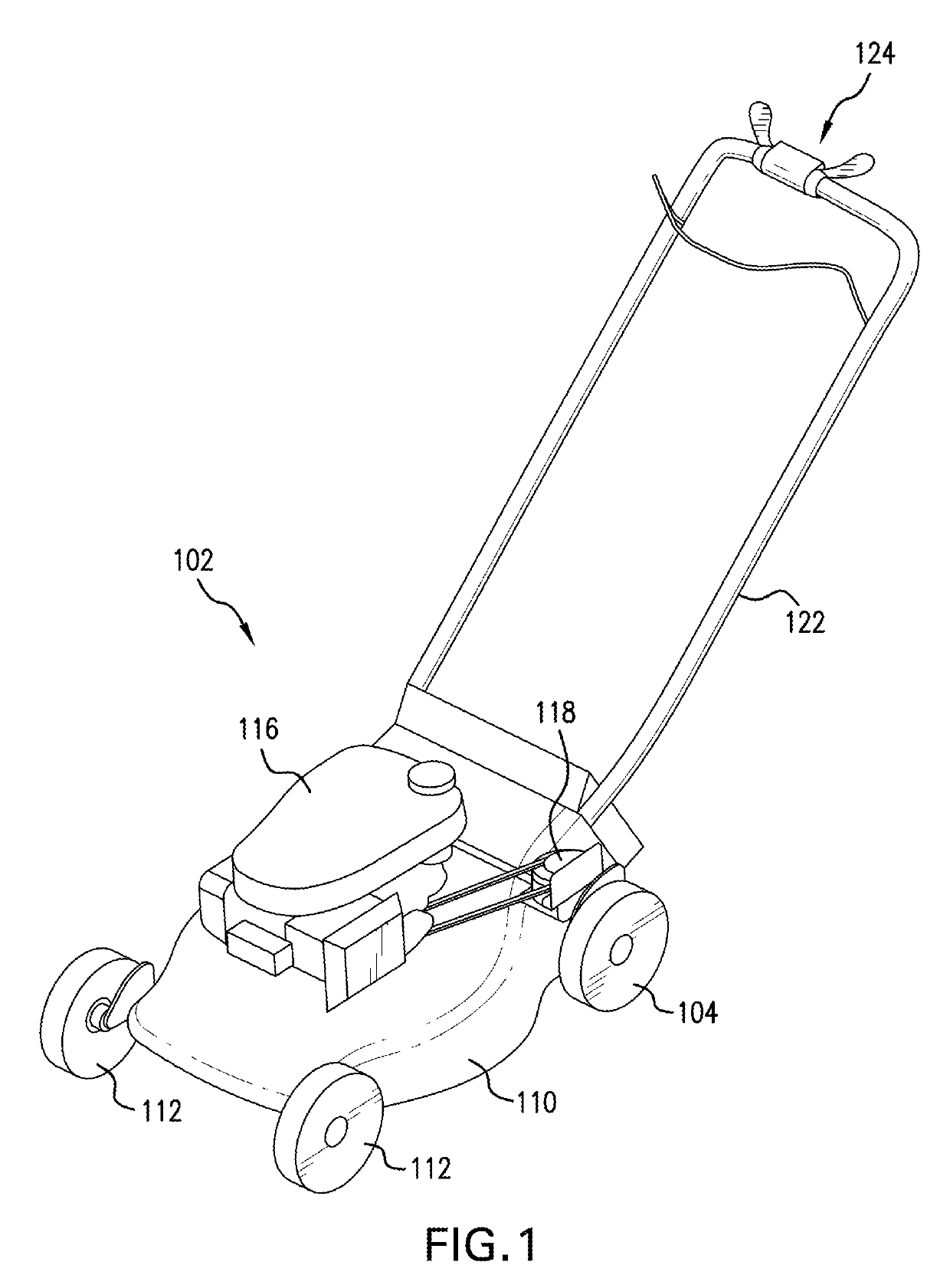
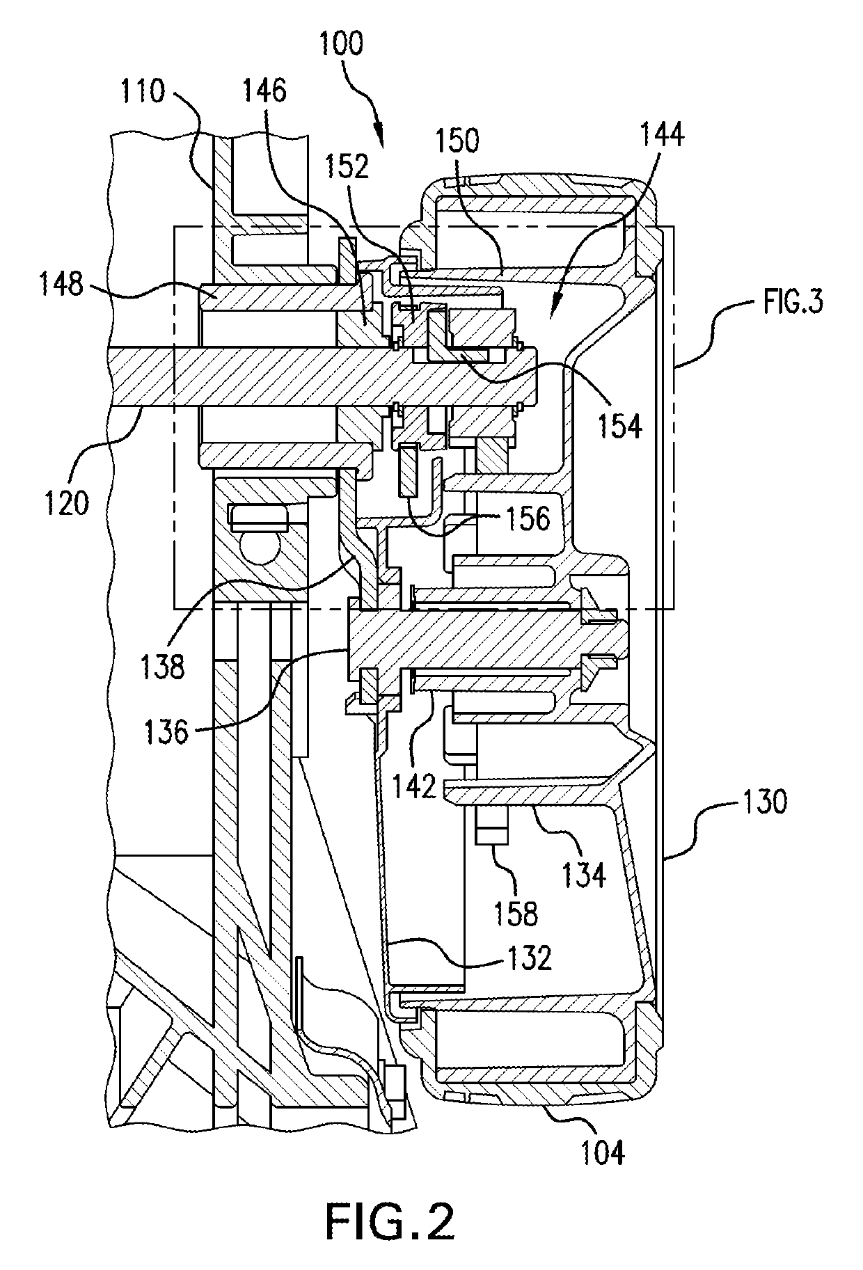
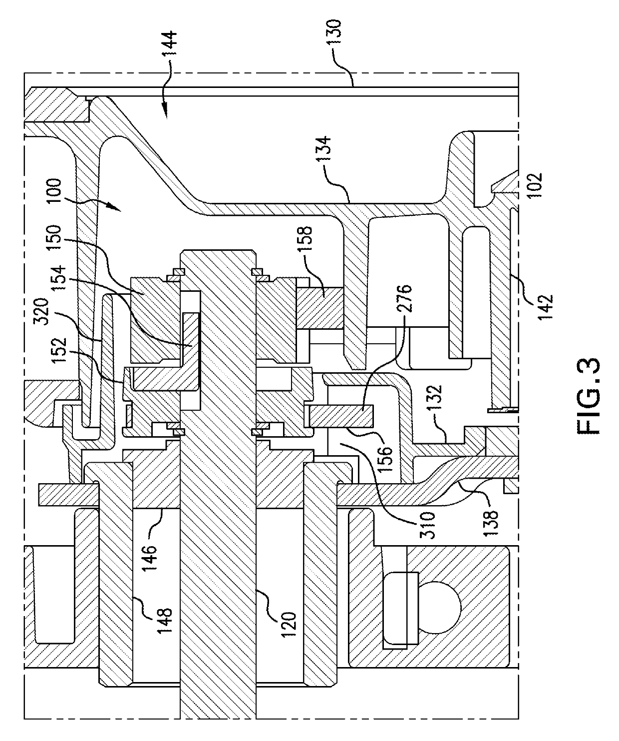
[0018]It should, of course, be understood that the description and drawings herein are merely illustrative and that various modifications and changes can be made in the structures disclosed without departing from the present disclosure. Referring now to the drawings, wherein like numerals refer to like parts throughout the several views, the present disclosure relates to a transmission 100 for a manually operated wheeled machine 102 having a drive condition and a freewheeling condition. As used herein, the drive condition refers to a condition of the wheeled machine where the transmission 100 is in an engaged state and torque is transmitted to at least one drive wheel 104 of the wheeled machine 102, and the freewheeling condition refers to a condition of the wheeled machine where the transmission 100 is in a disengaged state and at least one drive wheel 104 can freely rotate in both forward and rearward directions. FIG. 1 shows the application of the transmission 100 to a self-prope...


PUM


Abstract

A transmission for a manually operated wheeled machine includes an output shaft having a close-ended axial channel. A drive gear mounted on the output shaft includes an engaging groove. A ratchet is received in the channel and is in engagement with the engaging groove. A holder mounted on the output shaft includes a relief that receives the ratchet. A friction member applies radial friction to the holder to temporarily prevent rotation of the holder with the output shaft in a drive condition of the machine moving the ratchet into engagement with the engaging groove, and in the drive condition the drive gear and holder rotate with the output shaft. In a freewheeling condition of the machine the output shaft is stationary, and an overdrive of the drive gear disengages the ratchet from the engaging groove allowing for free rotation of the drive gear about the stationary output shaft.

Description

BACKGROUND[0001]Currently, the drive system of a wheeled machine, for example a lawnmower, includes a transmission and wheels driven by a pinion on the output shaft of the transmission. In order to minimize friction when the user pushes the lawnmower forward, simple ratchet mechanisms have been used inside the pinion mounted on the transmission output shaft. This allows for one-way driving of the wheels by the transmission and low friction in the forward direction. However, if the user wants to pull the lawnmower backwards, the ratchets do not disengage from the transmission output shaft. This causes high roll-back friction that the user must overcome to move the lawnmower backwards. In many cases, the pullback load is high enough to cause customers to complain about high load.[0002]It is known to use a combination of mechanisms to allow freewheeling when the transmission is not driving the system, and many of these designs are contained within the transmission itself. The internal-...

Claims


Application Information

Patent Timeline
Patent Type & Authority Applications(United States)
IPC IPC(8): F16D41/12A01D34/69
CPCA01D2101/00A01D2034/6843F16D41/06F16D2041/0608A01D2034/6837F16D2041/0603A01D34/69F16D41/12F16D41/069F16D41/14
Inventor VAUGHN, CHRISTOPHER W.LENFERT, NATHANIEL
Owner HONDA MOTOR CO LTD
Why Eureka
Try Eureka