
Abnormal signal orientation method in pipeline

An abnormal signal and pipeline technology, applied in pipeline systems, gas/liquid distribution and storage, mechanical equipment, etc., can solve problems such as inability to meet

Active Publication Date: 2014-08-20
BEIJING UNIV OF CHEM TECH
View PDF4 Cites 0 Cited by
  • Summary
  • Abstract
  • Description
  • Claims
  • Application Information

AI Technical Summary

Problems solved by technology

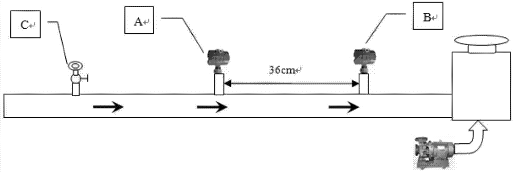
[0005] However, due to the existence of interference signals, the limitation of sampling accuracy and the limitation of sampling period, in order to accurately determine the propagation direction of abnormal signals, the installation distance between the two transmitters is actually required to be much larger than the above theoretical value
The installation spacing requirements of two adjacent transmitters are far from being met by the existing stations and valve rooms, so that the propagation direction of abnormal signals in the pipeline cannot be well determined in actual work, nor can it be satisfied. practical work needs

Method used


Image

  • Abnormal signal orientation method in pipeline
  • Abnormal signal orientation method in pipeline
  • Abnormal signal orientation method in pipeline

Examples


Embodiment Construction

[0072] In order to make the purpose, technical solution and advantages of the present invention clearer, the implementation of the method for orienting abnormal signals in pipelines of the present invention will be further described in detail below in conjunction with the accompanying drawings. It should be understood that the specific embodiments described here are only used to explain the present invention, not to limit the present invention.

[0073] Such as Figure 6 As shown in the figure, it is a processing flow chart of the abnormal signal orientation method in the pipeline according to the embodiment of the present invention. As an implementable mode, the pipeline abnormal signal directional method in the embodiment of the present invention includes the following steps:

[0074] Step S100, use two transmitters preset at one end of the pipeline with a preset distance to sense the dynamic pressure signal or acoustic wave signal inside the pipeline, and sequentially and ...


PUM


Abstract

The invention provides an abnormal signal orientation method in a pipeline. The method comprises the following steps of: acquiring and extracting output signals of two transmitters of a preset time length as first acquired data; performing normalization processing, mean adjustment and bipolar processing of the output signals on two frames of data of the first acquired data to obtain second acquired data; searching a signal maximum extreme value from the two frames of data of the second acquired data according polarity of the signal and performing trailing edge processing of an abnormal signal on the two frames of data of the second acquired data to obtain third acquired data; performing forward and backward bidirectional one-time linear interpolation of M-1 points on any path of signal for the third acquired data to form two interpolation sequences; and calculating cross correlation coefficient curves of the two sequences and another signal sequence respectively to obtain propagation direction of a pipeline leakage signal. According to the method, the propagation direction of the abnormal signal in the pipeline can be reliably determined.

Description

technical field [0001] The present invention relates to the technical field of abnormal signal propagation and orientation in pipelines with short-distance installation intervals of double transmitters, in particular to the technical field of abnormal signal orientation in pipeline leakage location in pipeline networks such as natural gas and liquid transportation, especially to pipeline networks An anomaly signal orientation method in the pipeline to determine the propagation direction of the anomaly signal in the pipeline. Background technique [0002] As one of the five major transportation industries, pipeline transportation, such as natural gas transportation and liquid (such as sewage, oil, etc.) transportation, plays an irreplaceable role in national economic construction, especially urban construction. However, the pipeline network formed by these transportation pipelines Due to reasons such as long-term service, corrosion and aging, and man-made damage, leakage acci...

Claims


Application Information

Patent Timeline
Patent Type & Authority Patents(China)
IPC IPC(8): F17D5/06
Inventor 林伟国李明军贾景堃
Owner BEIJING UNIV OF CHEM TECH
Learn More