

Led lamp
A technology of LED lamps and LED chips, which is applied in the direction of lampshades, lighting and heating equipment, semiconductor devices of light-emitting elements, etc., can solve the problem of reducing the gorgeousness of lighting appliances, and achieve the effect of easy assembly and disassembly operations
- Summary
- Abstract
- Description
- Claims
- Application Information
AI Technical Summary
Problems solved by technology
Method used
Image

Examples
no. 1 example
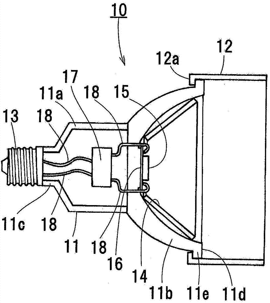
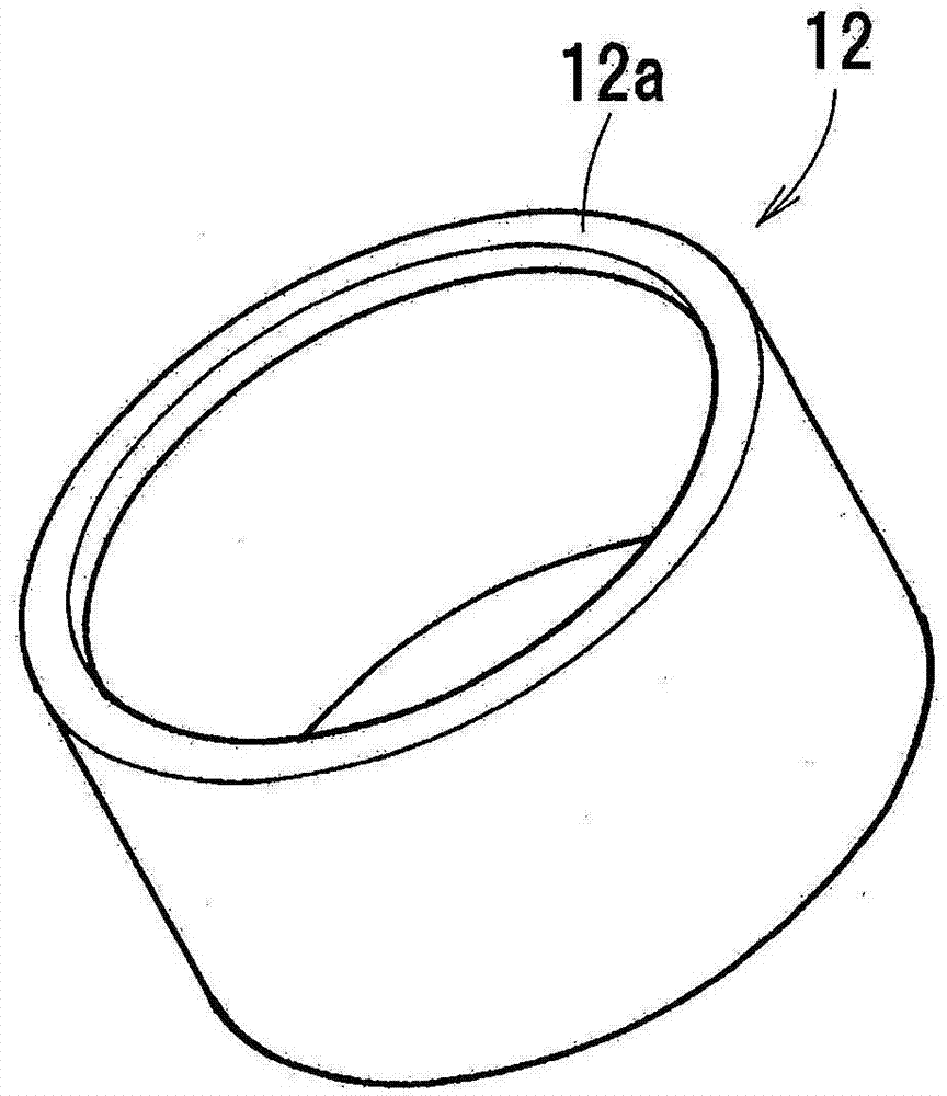
[0064] The present invention is described below based on the accompanying drawings, figure 1 The LED lamp 10 of the first embodiment of the present invention is shown in . in addition, figure 2 The lampshade 12 installed on the LED lamp is shown in . The LED lamp 10 includes a housing 11 made of a metal material such as aluminum having excellent thermal conductivity and heat dissipation, and a cylindrical hood 12 having openings at both ends.
[0065] The housing 11 is composed of a cylindrical housing main body 11a, a cup-shaped portion 11b provided on the front end of the housing main body 11a, and a small-diameter cylindrical portion 11c provided on the rear end of the housing main body 11a. A lamp cap 13 conforming to international standards is fixedly installed on the portion 11c.
[0066] A reflective layer 14 is formed on the inner peripheral surface of the cup-shaped portion 11 b of the housing 11 . A module circuit board 16 on which an LED chip 15 is mounted is f...
no. 2 example
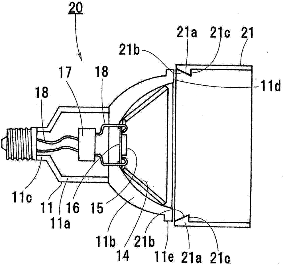
[0072] image 3 An LED lamp 20 according to a second embodiment of the present invention is shown in . in addition, Figure 4 The lampshade 21 installed on the LED lamp is shown in . Two hook pieces 21 a are formed at positions symmetrical to the center line of the globe 21 at the rear end portion of the globe 21 of the LED lamp 20 . Each hook piece 21a is composed of a tapered surface 21b and a stepped portion 21c continuous thereto, and the thickness of the hook piece 21a gradually increases from the rear end to the front end of the lampshade 21 due to the tapered surface 21b. Slits 21d are formed on both sides of each hook piece 21a so that the hook piece 21a is bent outward in the radial direction of the lampshade 21 .
[0073] In addition, since the other structures of the LED lamp 20 of 2nd Example are the same as the LED lamp 10 of 1st Example, the same code|symbol is attached|subjected to the same component, and description is abbreviate|omitted.
[0074] In the LE...
no. 3 example
[0077] Figure 5 A lampshade 31 installed on an LED lamp according to a third embodiment of the present invention is shown in . The globe 31 is an elastic opaque resin molded product, and its inner diameter is molded to be slightly smaller than the outer diameter of the flange portion 11e. Like the shade 12 of the LED lamp 10 of the first embodiment, an annular hook piece 31a is formed at the rear end. In addition, a slit 31b extending parallel to the center line of the lampshade 31 is formed on the peripheral surface, and the peripheral surface is divided by the slit 31b, so that the lampshade 31 can expand radially outward against the elastic force.
[0078] Since the shade 31 expands, it can be attached to the opening end 11d not only from the rear end side of the housing 11 but also from the opening end 11d side of the cup portion 11b. The expanded lampshade 31 is in pressure contact with the outer peripheral portion of the flange portion 11e of the opening end 11d by it...
PUM
 Abstract
Description
Claims
Application Information