A hydrodynamic cavitation device and system for heavy oil upgrading

A technology for hydrodynamic cavitation and heavy oil upgrading, which is applied in the petroleum industry, refined hydrocarbon oil, etc., can solve the problems of low saturated vapor pressure of heavy oil, high viscosity of heavy oil, high flow velocity, etc. The effect of reducing energy consumption

Active Publication Date: 2017-07-21
CHINA UNIV OF PETROLEUM (BEIJING)
View PDF2 Cites 0 Cited by
  • Summary
  • Abstract
  • Description
  • Claims
  • Application Information

AI Technical Summary

Problems solved by technology

Although this extreme environment can crack macromolecules, the saturated vapor pressure of heavy oil is low, and the flow velocity required to vaporize heavy oil is high, and the viscosity of heavy oil is very high, so it is quite difficult to achieve cavitation
At present, there is no relevant device for upgrading heavy oil by hydrodynamically cavitating heavy oil at a relatively low temperature (below 70°C)

Method used


Image

  • A hydrodynamic cavitation device and system for heavy oil upgrading
  • A hydrodynamic cavitation device and system for heavy oil upgrading
  • A hydrodynamic cavitation device and system for heavy oil upgrading

Examples


Embodiment 1

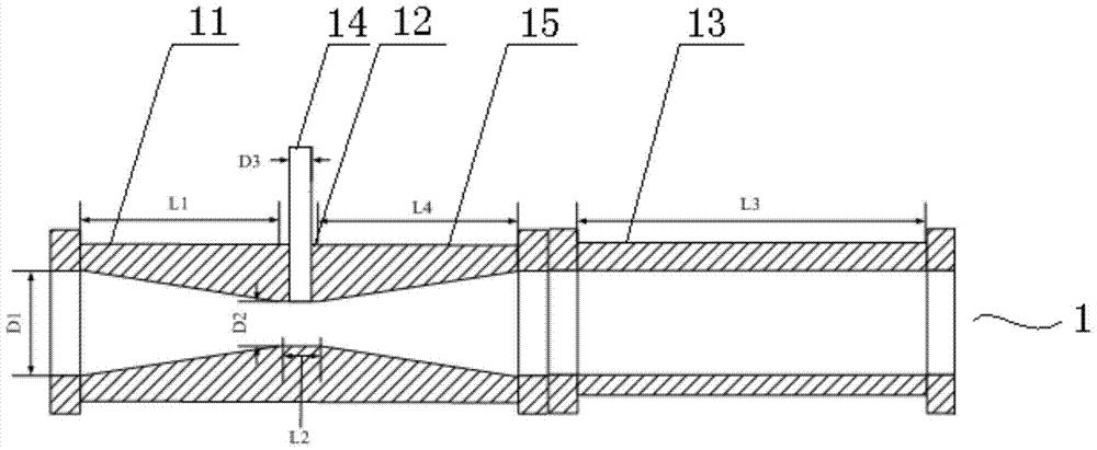
[0031] Such as figure 1 As shown, the hydraulic cavitation device 1 of this embodiment includes a heavy oil inlet section 11, a throat section 12, an expanding section 15 and a stabilizing section 13 arranged in sequence, each section is connected in sequence and communicated axially, and the flow area of ​​the throat section 12 is smaller than The flow area of ​​the inlet end of the heavy oil inlet section 11 and the outlet end of the enlarged section 15, the heavy oil inlet section 11 and the enlarged section 15 have trumpet-shaped through holes, and the small ends of the trumpet-shaped through holes are all set toward the throat section 12, and on the throat section 12 An auxiliary agent inlet section 14 communicating with the throat section 12 is arranged radially.

[0032] Specifically, the heavy oil inlet section 11, the throat section 12, and the expansion section 15 can be integrally formed, and the throat section 12 and the expansion section 15 are both cylindrical an...

Embodiment 2

[0038] Adopt the hydraulic cavitation device of embodiment 1 to carry out heavy oil reforming, difference is: D1 is 40mm, D2 / D1 is 0.3, D3 / D2 is 0.4, L1 / D1 is 2, L2 / D2 is 1, L3 / D1 is 5. L4 / D1 is 2, the inner diameter of the inlet end of the stabilizing section and the outlet end of the expanding section are both 40mm, and the heavy oil inlet section, throat section, expanding section and stabilizing section are integrally formed.

[0039] After the heavy oil is heated to about 50°C and pressurized to about 4MPa by a high-pressure pump, it is sent to the heavy oil inlet section of the hydraulic cavitation device. When the heavy oil reaches the throat section, dimethyl disulfide is sucked into the hydraulic air chamber through the auxiliary agent inlet section. In the gasification device, dimethyl disulfide is vaporized, and heavy oil and dimethyl disulfide undergo hydrodynamic cavitation, wherein, the addition amount of dimethyl disulfide is controlled so that the weight ratio o...

Embodiment 3

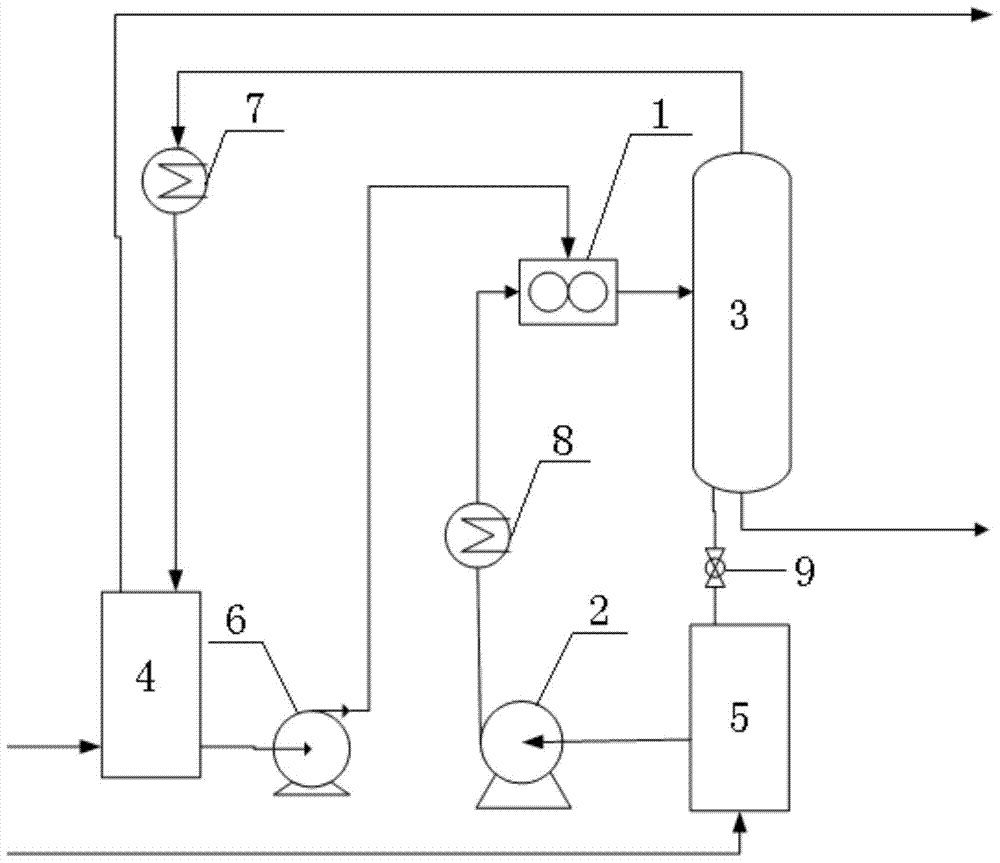
[0048] Such as figure 2 As shown, the hydraulic cavitation system for heavy oil upgrading in this embodiment includes a hydraulic cavitation device 1, a high-pressure pump 2 and a gas-liquid separation device 3, the high-pressure pump 2 is connected to the heavy oil inlet section of the hydraulic cavitation device 1, and the gas The liquid separation device 3 is connected with the stabilization section of the hydraulic cavitation device 1 . Specifically, the hydraulic cavitation device 1 may be the hydraulic cavitation device of Embodiment 1 or 2.

[0049] Further, the system also includes an auxiliary cavitation agent storage tank 4 and a heavy oil storage tank 5, the auxiliary cavitation agent storage tank 4 is connected to the auxiliary agent inlet section of the hydraulic cavitation device 1 through a pipeline, and the heavy oil storage tank 5 is connected to the high-pressure Pump 2 is connected. Moreover, a pump 6 may be provided on the pipeline between the auxiliary ...


PUM

PropertyMeasurementUnit
densityaaaaaaaaaa
boiling pointaaaaaaaaaa

Abstract

The invention provides a hydraulic cavitation device and system for upgrading heavy oil. The hydraulic cavitation device of the present invention includes a heavy oil inlet section, a throat section, an expanding section and a stabilizing section arranged in sequence, each section is connected in sequence and communicated in the axial direction, and the flow area of ​​the throat section is smaller than the inlet end of the heavy oil inlet section and the flow area of ​​the outlet end of the enlarged section, the heavy oil inlet section and the enlarged section both have a trumpet-shaped through hole, and the small ends of the trumpet-shaped through-holes are all set toward the throat section, and in the throat section An auxiliary agent inlet section communicating with the throat section is arranged radially on the upper side. The device and system of the present invention can realize reforming of heavy oil by hydraulic cavitation at relatively low temperature, and can obtain good reforming and viscosity reducing effects.

Description

technical field [0001] The invention relates to a heavy oil reforming device, in particular to a hydraulic cavitation device and system for heavy oil reforming. Background technique [0002] Heavy oil refers to the density greater than 0.93g / cm 3 , Crude oil with a boiling point higher than 350°C under normal pressure. Due to the high content of long-chain macromolecules, colloids and asphaltenes, heavy oil has high viscosity and poor fluidity, which has adverse effects on crude oil transportation. Therefore, heavy oil needs to be modified such as viscosity reduction. At present, the commonly used heavy oil viscosity reduction methods at home and abroad can be divided into two categories: physical methods and chemical methods. [0003] Physical viscosity reduction methods mainly include heating viscosity reduction method, thin oil viscosity reduction method, low viscosity liquid ring viscosity reduction method, etc. The heating visbreaking method is mainly to obtain enoug...

Claims


Application Information

Patent Timeline
Patent Type & Authority Patents(China)
IPC IPC(8): C10G31/00
Inventor 郭绪强孙厚刚张永学
Owner CHINA UNIV OF PETROLEUM (BEIJING)
Why Eureka
Try Eureka