Clutch straight rod short-circuit grounding device

A grounding device, a straight-rod technology, applied in the direction of circuit, connection, conductive connection, etc., can solve the problems of inconvenient operation, poor safety, easy to fall off, etc., and achieve the effect of low production cost, easy operation and high safety performance

Inactive Publication Date: 2016-06-22
何国飞
View PDF7 Cites 0 Cited by
  • Summary
  • Abstract
  • Description
  • Claims
  • Application Information

AI Technical Summary

Problems solved by technology

[0008] The present invention aims at the short circuit grounding device in the prior art, which is easy to fall off, poor in safety and inconvenient to operate, and provides a clutch straight rod type short circuit grounding device to solve the above problems

Method used


Image

  • Clutch straight rod short-circuit grounding device
  • Clutch straight rod short-circuit grounding device
  • Clutch straight rod short-circuit grounding device

Examples


Embodiment 1

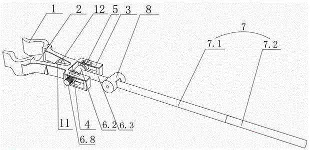
[0036] Such as Figure 2-5As shown, the clutch straight rod type short-circuit grounding device of the present invention includes a wire end clamp A and a handle 7. The wire end clamp A includes a pair of splints 1 connected to the steering shaft by means of a support piece 11 and an arc-shaped bite 2 is provided on the upper part. The tail A of the wire end clamp is provided with a pair module 3, and a movable nut 4 is arranged in the pair module 3, and the movable nut 4 is connected with the movable piece 5 arranged on the pair module 3 through a screw, and the movable nut 4 can rotate laterally along the screw rod , the movable piece 5 can slide on the pair of modules 3; the telescopic mechanism 6 includes a pair of telescopic rods 6.1, a cover cylinder 6.2, a guide cylinder 6.3, a rotating rod 6.4, and a side cylinder 6.5. The end of the guide cylinder 6.3 is connected with the cover cylinder 6.2, and the side The tube 6.5 is hollow, and it can be stretched in the cover tu...

Embodiment 2

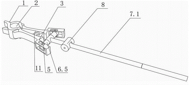
[0041] Such as Figure 6-7 As shown, the difference from Embodiment 1 is that the inner side wall of the one splint 1 is also provided with a depressing tongue 13, which is arranged between the rotating shaft 12 and the arc-shaped bite 2, and the other splint 1 is correspondingly A tongue depressing through hole is provided. The effect of this pressure 13 is, when wire end wire clamp A is in open state, depressing tongue 13 is used for propping up wire end wire clamp A, moves back and forth when avoiding expansion rod 6.1 to tighten up. When it is necessary to loosen the splint 1 for clamping, the pressing tongue 13 contacts the wire, and the wire terminal clamp A can be released. The remaining technical principles are the same as in Embodiment 1.

Embodiment 3

[0043] The difference from Embodiment 1 is that the telescopic rod 6.1, the rotating rod 6.4, and the gripping rod 7.3 are threaded as a whole, and the transmission mode is worm gear transmission, and the rest of the operation modes are the same as in Embodiment 1.


PUM


Abstract

The invention discloses a clutch straight pole type short circuit grounding device which comprises a wire end cable cleat (A) and a holding rod (7), wherein the wire end cable cleat (A) comprises a pair of clamping plates (1), the clamping plates (1) rotate with the help of a revolving shaft, and arc-shaped occlusions (2) are arranged on the upper portions of the clamping plates (1). The clutch straight pole type short circuit grounding device is characterized in that opposite die blocks (3) are arranged on the tail portion of the wire end cable cleat (A), moving nuts (4) are arranged in the opposite die blocks (3), the moving nuts (4) are movably connected with the opposite die blocks (3), and the moving nuts (4) can horizontally rotate and slide in the opposite die blocks (3). A telescoping mechanism (6) is fixedly connected with the moving nuts (4), the telescoping mechanism (6) is connected with the holding rod (7), and the holding rod (7) is provided with a control mechanism which can control the telescoping mechanism (6) to stretch out and draw back. The clutch straight pole type short circuit grounding device has the advantages of being good in safety performance. Due to the fact that the wire end cable cleat is controlled by people to clamp or loosen wires, the condition that the wire end cable cleat automatically fall off is not enabled to emerge.

Description

technical field [0001] The invention relates to a safety tool or appliance for overhauling electric power, in particular to a clutch straight-rod type short-circuit grounding device. Background technique [0002] In existing short-circuit grounding devices, such as figure 1 The grounding wire 100 shown is a safety tool used to temporarily ground the power equipment that has been powered off when the power equipment is overhauled. The induced electric impact generated to prevent the occurrence of electric shock accidents for staff. Installing a grounding wire is a necessary safety technical measure to change the power equipment from the operating state to the maintenance state. The grounding wire 100 is connected to the wire and the earth by means of the wire end wire clamp 200 and the grounding end wire clamp 300 respectively. However, in the prior art The wire end clamp includes a pair of splints 600 connected by rotation shaft 400 and the upper part is provided with an a...

Claims


Application Information

Patent Timeline
Patent Type & Authority Patents(China)
IPC IPC(8): H01R11/14H01R4/48H01R43/00
Inventor 宋倩怡何国飞莫震宁
Owner 何国飞
Why Eureka
Try Eureka