


Quick Research
Generate reliable direction feasibility study reports for your R&D in just a few steps.

Technical Q&A
Discover and master advanced knowledge NOW. Basics, ideas, possibilities, all at once.

Find Solutions
As an expert in R&D theories, this can generate solutions to your technical problems instantly.

Evaluate Feasibility
Analyze your overall solution with one click, know your potential R&D risks in advance.

Monitor Landscape
Get weekly tech updates, stay abreast of the latest tech innovations and key insights.
Converter system and method for operating such a converter system
A technology of converter, DC voltage, applied in the field of converter system
- Summary
- Abstract
- Description
- Claims
- Application Information
AI Technical Summary
Problems solved by technology
Method used
Image

Examples
Embodiment Construction
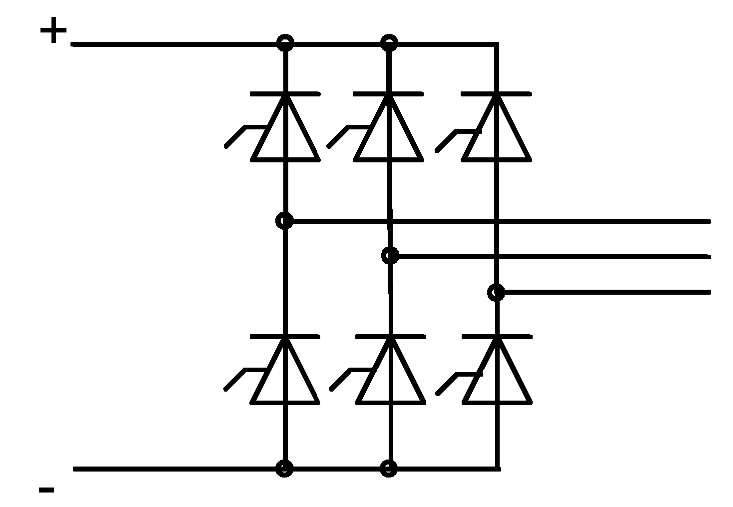
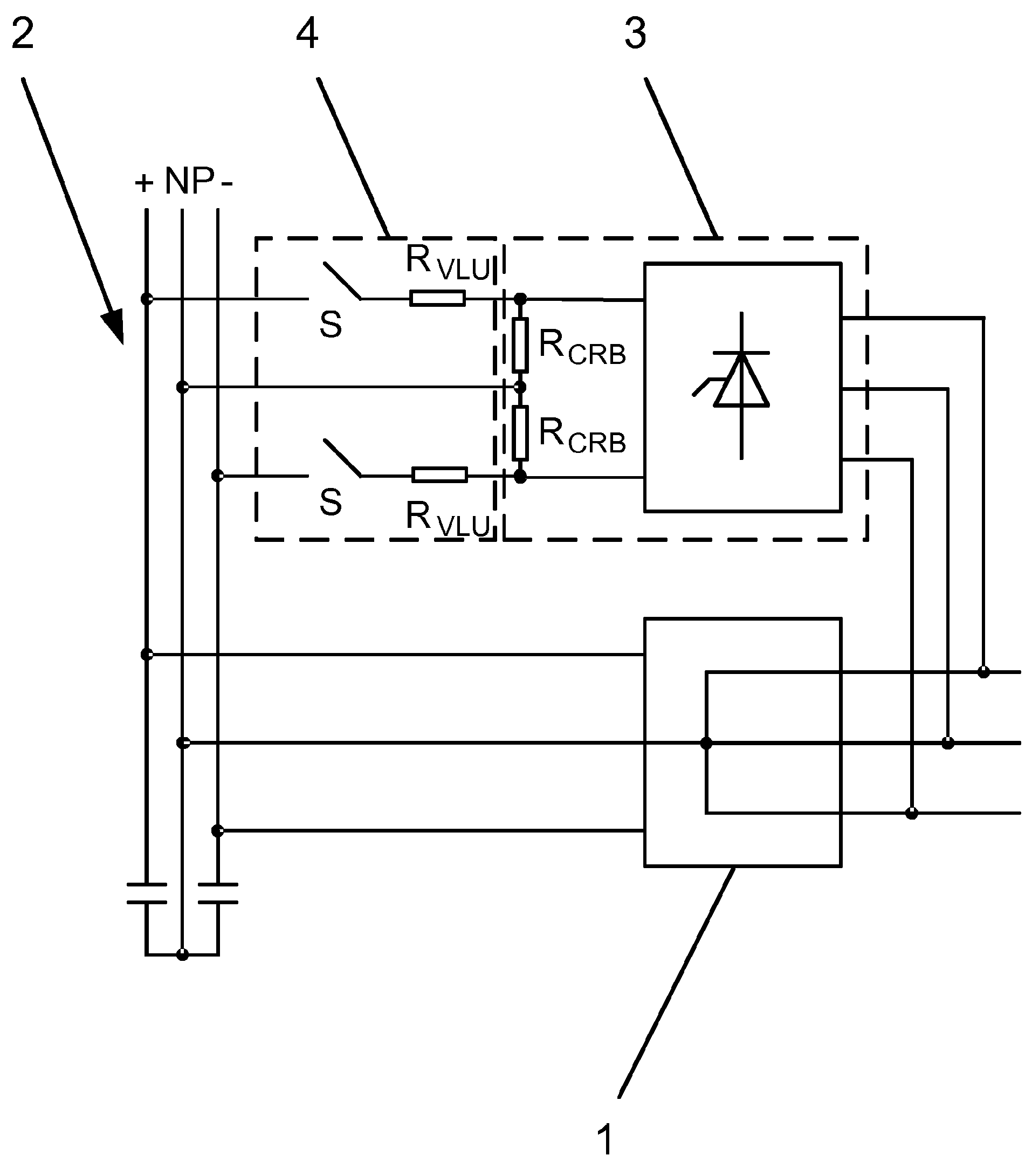
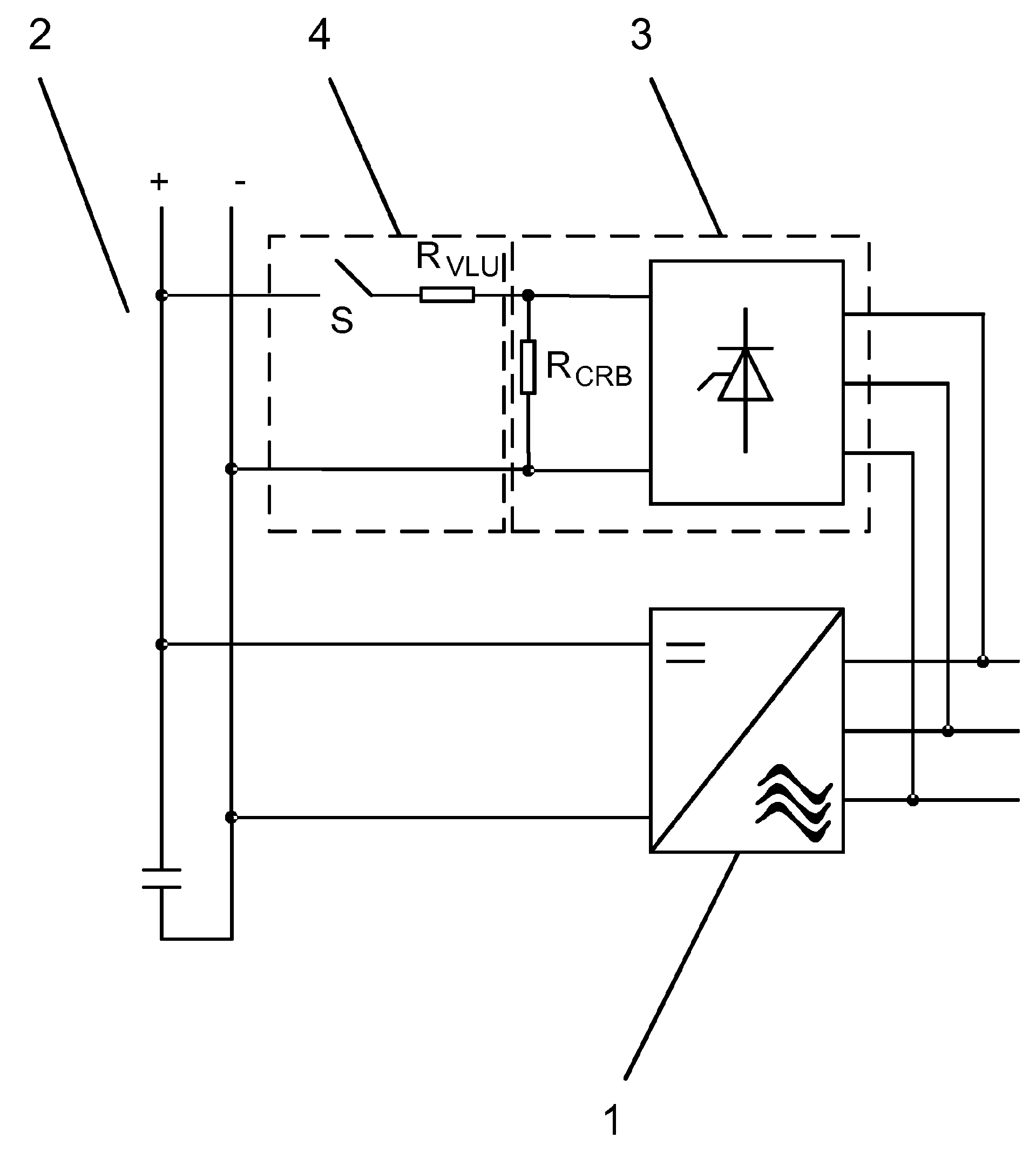
[0023] FIG. 1 shows a first embodiment of a converter system according to the invention, in particular for switching three voltage levels. The converter system according to the invention for switching generally at least three voltage levels comprises a converter unit 1 to which a direct voltage circuit 2 is connected on the direct voltage side, the direct voltage circuit 2 having Voltage zero point NP, and a short circuit 3 is connected to the AC voltage side of the converter unit. The shorting circuit 3 has a plurality of thyristors and at least two shorting resistors R CRB. An exemplary embodiment of a thyristor circuit of the short circuit 3 is shown in FIG. 4 . According to the invention, a voltage limiting unit 4 for limiting the overvoltage of the DC voltage circuit 2 is connected to the DC voltage circuit 2, wherein the voltage limiting unit 4 is connected to at least two short-circuit resistors R CRB connect. Typically, the voltage limiting unit 4 is used to limit ...
PUM
 Abstract
Description
Claims
Application Information
 - R&D Engineer
- R&D Manager
- IP Professional
- Industry Leading Data Capabilities
- Powerful AI technology
- Patent DNA Extraction
Browse by: Latest US Patents, China's latest patents, Technical Efficacy Thesaurus, Application Domain, Technology Topic, Popular Technical Reports.
© 2024 PatSnap. All rights reserved.Legal|Privacy policy|Modern Slavery Act Transparency Statement|Sitemap|About US| Contact US: help@patsnap.com