Guide devices for power tools

A technology for guiding devices and power tools, which can be used in portable motorized devices, sawing machine devices, manufacturing tools, etc., and can solve the problems that ruler boards cannot be used and connectors cannot be installed on them.

Active Publication Date: 2013-04-17
MAKITA CORP
View PDF9 Cites 0 Cited by
  • Summary
  • Abstract
  • Description
  • Claims
  • Application Information

AI Technical Summary

Problems solved by technology

Therefore, if the model of the power tool is changed, the intervals of the connecting part mounting parts provided on it will also be different. At this time, the connector cannot be installed on it, so that the scale plate cannot be used. Therefore, from the perspective of versatility Consider, to be improved

Method used


Image

  • Guide devices for power tools
  • Guide devices for power tools
  • Guide devices for power tools

Examples


Embodiment Construction

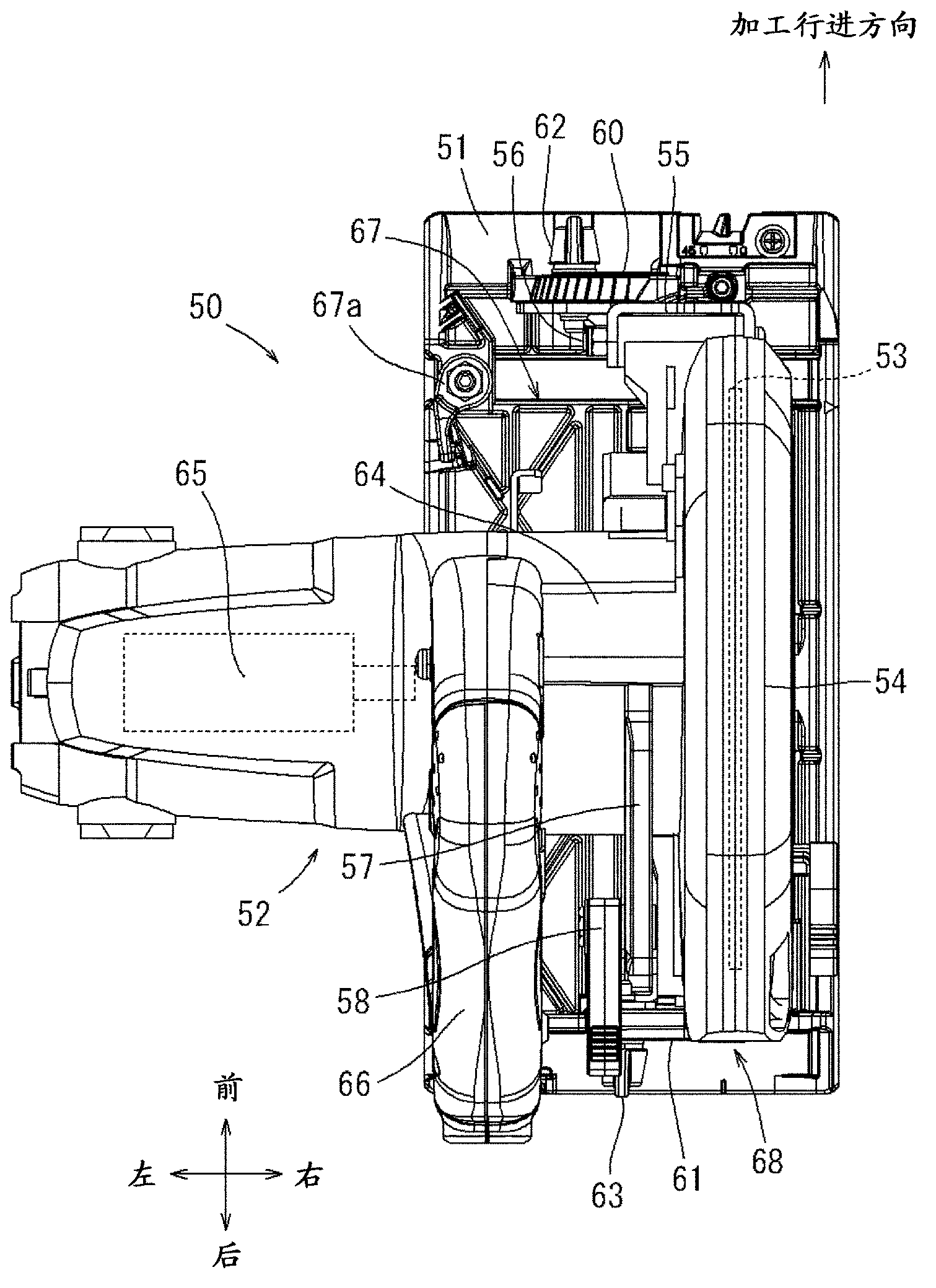
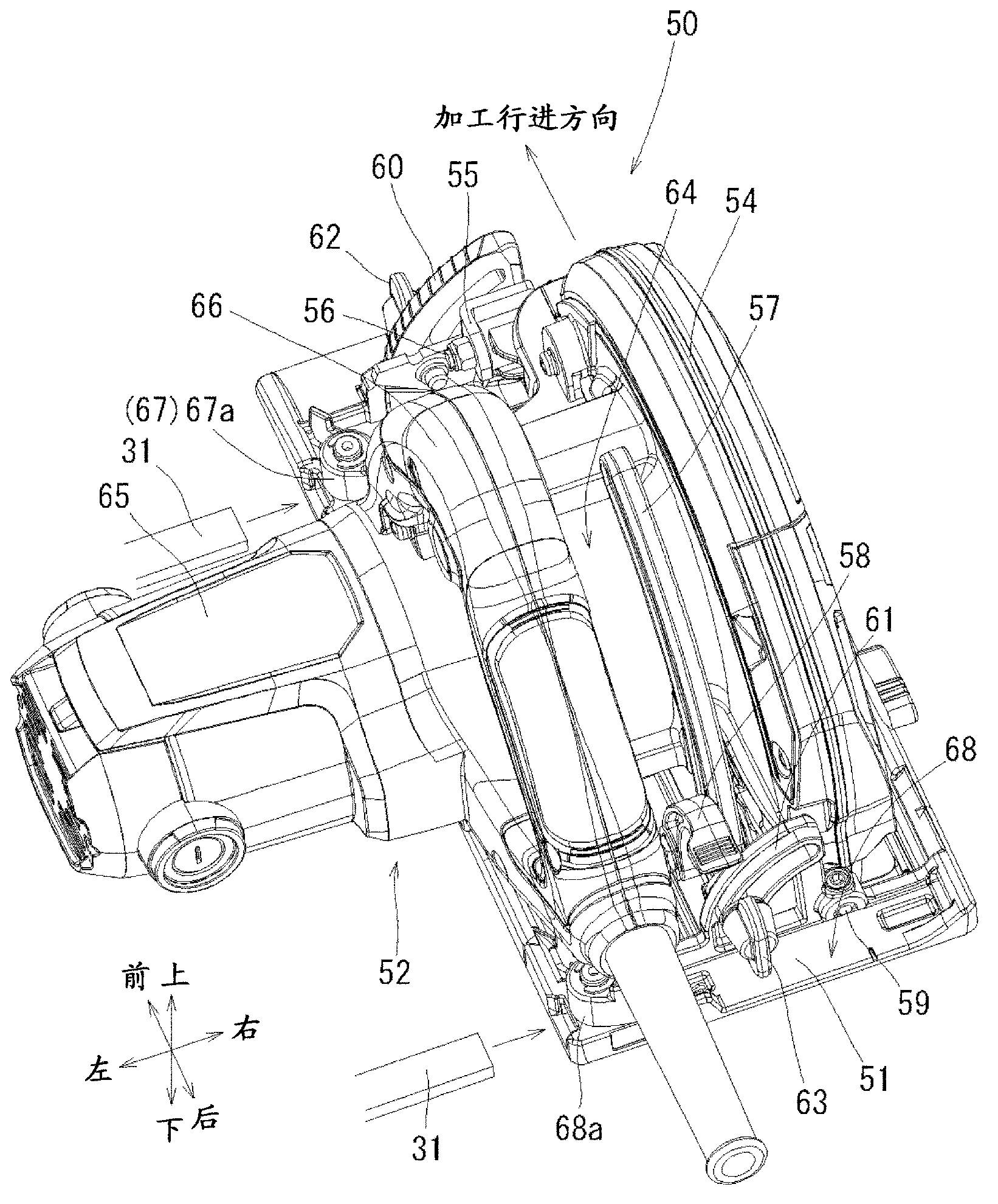
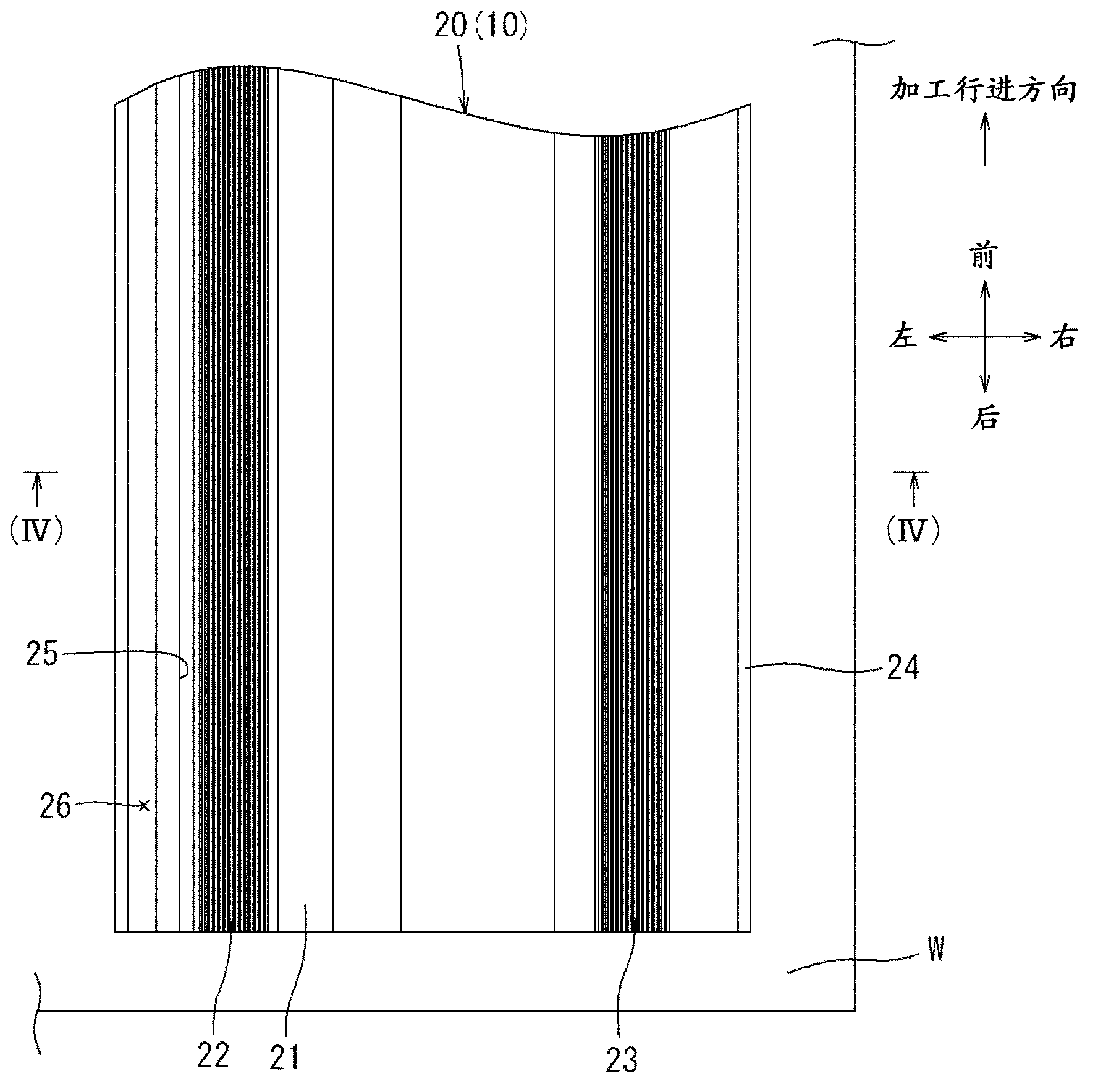
[0042] According to the following Figure 1~Figure 17 Specific embodiments of the present invention will be described. In the following embodiments, a cutting tool 50 called a portable circular saw will be described as an example of a power tool. The guide device 10 described later is attached to the cutting tool 50 , so that the cutting tool 50 can be precisely moved linearly over a long distance to perform high-precision cutting processing. In this embodiment, an improvement is made to the guiding device for guiding the cutting tool 50, while the cutting tool 50 itself adopts the existing structure, and no special improvement is necessary in this embodiment. Therefore, the cutting tool 50 is only briefly described below.

[0043] In the following description, the front-rear, left-right directions of components and the like are defined on the basis of the direction in which the cutting tool 50 is moved to perform the cutting process. figure 1 and figure 2 The cutting too...


PUM


Abstract

A guide device (10) may include a ruler plate (20) adapted to be fixed in position relative to the workpiece (W), an adapter base (30) adapted to support the power tool (50, 70) and movable in a process proceeding direction relative to the ruler plate (20), and a plurality of connection members (31, 43) for connecting the adapter base (30) to the power tool (50, 70). The plurality of connection members may include a front connection member (31, 43) and a rear connection member (31, 43) positioned on a rear side of the front connection member with respect to the process proceeding direction. A distance between the front connection member and the rear connection member can be changed.

Description

technical field [0001] The present invention relates to a guiding device for guiding a power tool. The power tool is a portable power tool, such as a portable circular saw or a wire saw. In the cutting process, the above-mentioned guide device guides the cutting of the power tool so that it can travel in a straight line with respect to the workpiece to be cut. Background technique [0002] For example, in the case of a portable circular saw having a base for placing on the workpiece to be cut and a tool body supported on the base, the portable circular saw is used to straighten the workpiece for long distances. When cutting, you need to use a ruler (strip)-shaped ruler. In the prior art, such a ruler plate is disclosed in the following Patent Document 1. According to the technique disclosed in Patent Document 1, the upper surface of the ruler plate is provided with a guide protrusion extending in the longitudinal direction thereof, and on the other hand, the lower surface ...

Claims


Application Information

Patent Timeline
Patent Type & Authority Applications(China)
IPC IPC(8): B25F5/00B23D47/02
CPCB23Q9/0042
Inventor 和田有希稻吉广共
Owner MAKITA CORP
Why Eureka
Try Eureka