Method of cooling air in a vehicle and air conditioning system for a vehicle

A technology for vehicle air conditioning and vehicles, which is applied to vehicle components, air handling equipment, heating/cooling equipment, etc., and can solve problems such as difficult to manage vehicle energy loads

Active Publication Date: 2013-04-17
ALSTOM TRANSPORT TECH SAS +1
View PDF5 Cites 4 Cited by
  • Summary
  • Abstract
  • Description
  • Claims
  • Application Information

AI Technical Summary

Problems solved by technology

This further makes it difficult to manage the energy load of the vehicle

Method used


Image

  • Method of cooling air in a vehicle and air conditioning system for a vehicle
  • Method of cooling air in a vehicle and air conditioning system for a vehicle
  • Method of cooling air in a vehicle and air conditioning system for a vehicle

Examples


Embodiment Construction

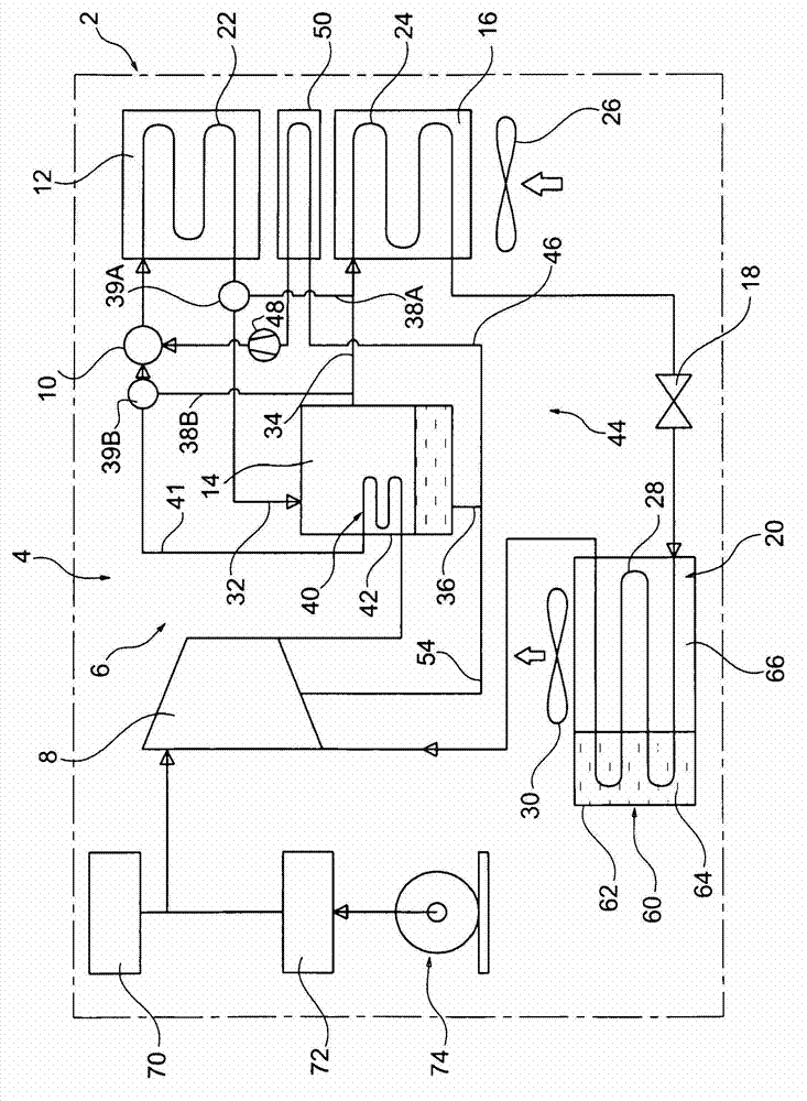
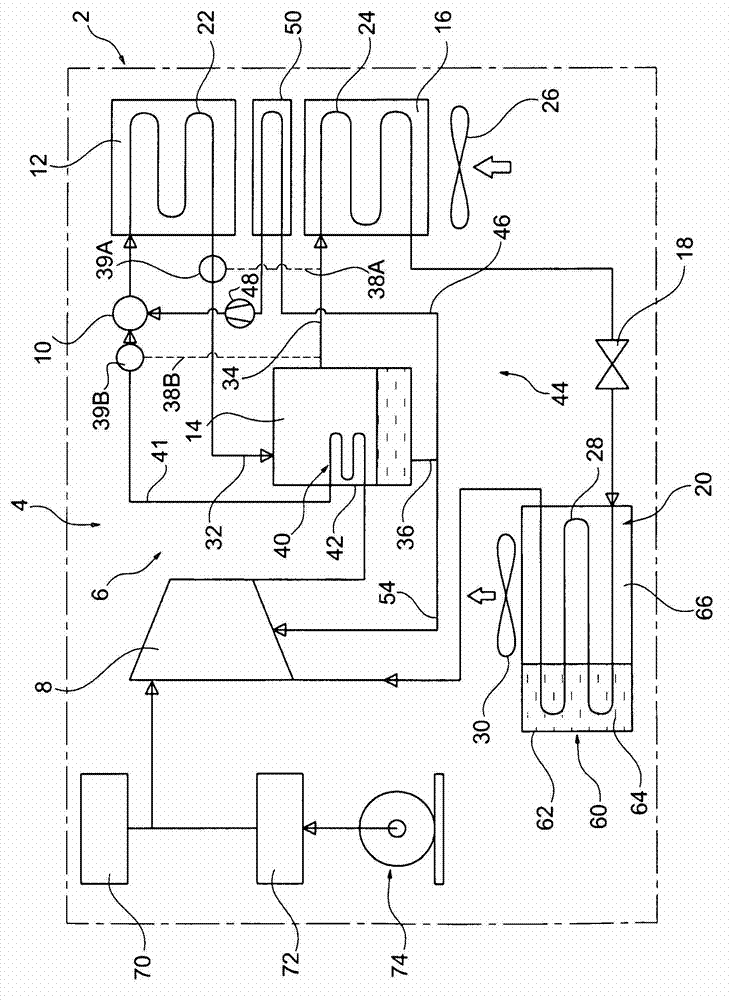
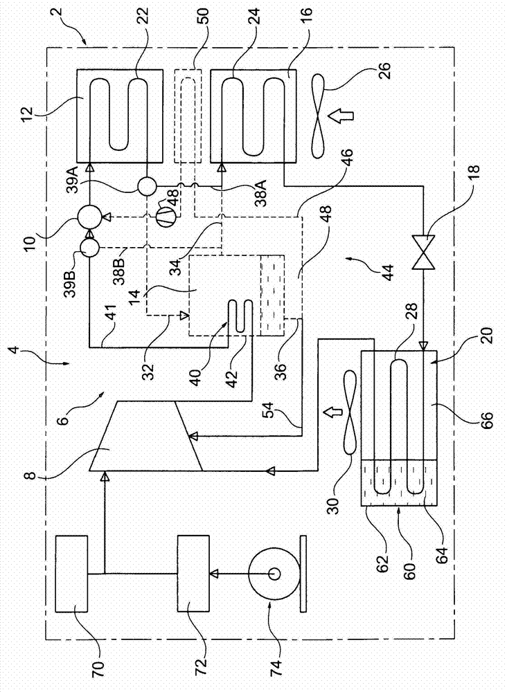
[0035] Such as figure 1 As shown, a vehicle 2 , such as a railcar, includes an air conditioning system 4 for conditioning the air in the passenger compartment of the vehicle 2 .

[0036] The air conditioning system 4 is used to run a refrigeration cycle with a refrigeration fluid or refrigerant for generating and transferring cold to the air blown into the passenger compartment.

[0037] The air conditioning system 4 includes a refrigerant circuit 6 for circulating refrigerant. The refrigerant circuit 6 includes a compressor 8, a mixer 10, an absorption heat exchanger or "absorber" 12, a separator 14, a condensing heat exchanger or "condenser" 16, an expansion device 18 and an evaporating heat exchanger or "evaporator". device" 20.

[0038] The compressor 8, mixer 10, absorber 12, separator 14, condenser 16, expansion device 18 and evaporator 20 are fluidly connected in series in a loop arrangement for circulating the refrigerant.

[0039] The absorber 12 is a heat exchange...


PUM


Abstract

The invention is a method of cooling air in a vehicle using a cold storage unit (60) in the refrigeration cycle. The air conditioning system and its cold storage unit is adapted to work according to the operation of the vehicle. The method produces cold in excess to be stored in the cold storage unit (60), using the phase change heating of materials, in at least an operation mode of the system. This cold in excess allows to cool the supply air to the comfort volume, in at least one other operation mode. These charge / discharge of the cold storage unit (60) and the refrigeration cycle associated could correspond to a minimization of consumption criteria of the vehicle, for example, a regenerative braking period and a traction / coasting period, or alternatively, according to the optimization of the variable condenser capacity of the refrigeration cycle.

Description

technical field [0001] The present invention relates to a method of cooling air in a vehicle and to a vehicle air conditioning system. Background technique [0002] Public transport vehicles such as buses, trains and trams often have high frequency start / stop cycles with short travel times. This makes it difficult to control air-conditioning systems to provide thermal comfort to passengers or to cool closed spaces that house heat-generating equipment, such as technical rooms, while limiting the energy consumption of the air-conditioning system. It is difficult to obtain the coefficient of performance (COP) of the air conditioning system over the entire travel time period. This further makes it difficult to manage the energy load of the vehicle. Contents of the invention [0003] The purpose of the invention is to propose a method of cooling the air in a vehicle which reduces energy consumption while allowing good thermal comfort for the passengers. [0004] To this end,...

Claims


Application Information

Patent Timeline
Patent Type & Authority Applications(China)
IPC IPC(8): B60H1/04
CPCB60H1/005B60H1/00764
Inventor R·巴尔巴马尔蒂J·M·纳森塔阿特梅拉R·博世托斯
Owner ALSTOM TRANSPORT TECH SAS
Why Eureka
Try Eureka