
Self-lock device of sliding door

A technology of self-locking device and sliding door, which is applied in the direction of non-mechanical transmission-operated locks, building locks, buildings, etc., and can solve the threat to passengers' personal and property safety, undesigned sliding door locking device, safety hazards in the use of sliding doors, etc. problem, to achieve the effect of long service life, simple structure and good locking effect

Active Publication Date: 2013-04-17
四川久远新方向智能科技有限公司
View PDF6 Cites 5 Cited by
  • Summary
  • Abstract
  • Description
  • Claims
  • Application Information

AI Technical Summary

Problems solved by technology

[0003] However, most of the existing rail transit screen door systems are not designed with a locking device when the sliding door is closed, and non-professional staff such as passengers or cleaners can open the sliding door at the platform side at will, which brings great safety. Hidden danger
[0004] In addition, the sliding door closing and locking devices currently on the market mainly use the mechanical transmission mechanism for auxiliary control of the opening and closing process. Due to the influence of the structure, false locks are prone to occur. At the same time, due to the limitation of the mechanical transmission process, when opening There will also be response lag and untimely phenomena, which will bring safety hazards to the use of sliding doors, and will also threaten the personal and property safety of passengers.

Method used


Image

  • Self-lock device of sliding door
  • Self-lock device of sliding door
  • Self-lock device of sliding door

Examples


Embodiment Construction

[0025] The technical solution of the present invention will be further described in detail below in conjunction with the accompanying drawings, but the protection scope of the present invention is not limited to the following description.

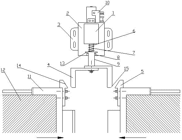
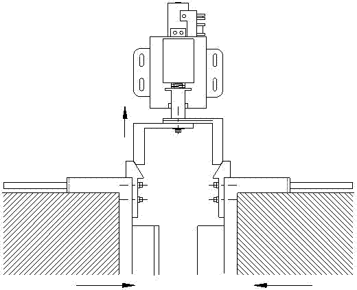
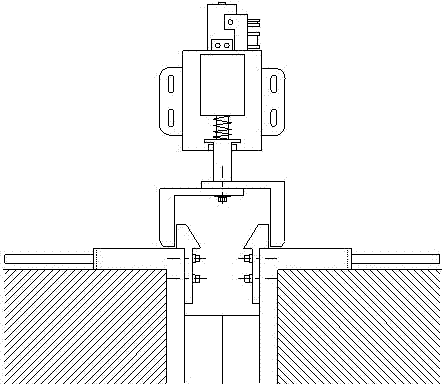
[0026] Such as figure 1 As shown, the sliding door self-locking device comprises a lock body 1, a lock housing 2, a lock body mounting seat 3, a controller 10 for driving and controlling the lock body 1, a dead bolt 5 fixedly installed on the top of the sliding door 12 and The claw 4 used to clamp the deadbolt 5; the control signal output of the controller 10 is connected with the lock body 1 to control the power-on state of the lock body 1. When the lock body 1 is powered on, it has an adsorption force to the magnetic core 6, and the lock body 1 When the power is cut off, the magnetic core 6 loses its adsorption force. The lock body 1 is fixedly installed in the lock case 2, and the lock case 2 is fixedly installed on the lock body mounti...


PUM


Abstract

The invention discloses a self-lock device of a sliding door. The device comprises a lock body (1), a lock case (2), a controller (10), a bolt (5) and a lock jaw (4); the lock body is fixedly arranged inside the lock case (2), the lower portion of the lock case (2) is provided with a sleeve (8), a connecting rod (9) is slidingly arranged inside the sleeve (8), the lock jaw (4) is fixedly arranged on the bottom end of the connecting rod (9), the top end of the connecting rod (9) is fixedly provided with a magnetic core (6); the bolt (5) is arranged on a sliding door (12) through a bolt installing seat (11). The sliding door can be locked when closed and can effectively avoid the potential security problems that non-professional workers fall on tracks or litter on the racks to affect train driving when standing casually on platform and opening the sliding door. The self-lock device of the sliding door has the advantages of being simple in structure, low in manufacturing cost, reasonable and stable in structural design, good in locking effect, long in service life, convenient to mount, maintain and dismount, rapid in corresponding speed, low in energy consumption during self-locking process and low in operating cost.

Description

technical field [0001] The invention relates to a sliding door self-locking device. Background technique [0002] With the rapid development of social economy and urban construction level, rail transit is becoming more and more important in urban public transportation system. The screen door system used in rail transit is a typical electromechanical integration product. It is arranged along the edge of the rail transit platform to isolate the station platform from the locomotive tunnel. It can not only prevent people and objects from falling on the track, but also reduce air conditioning in the station. The operating energy consumption of the ventilation system can reduce the impact of train operation noise on the station. [0003] However, most of the existing rail transit screen door systems are not designed with a locking device when the sliding door is closed, and non-professional staff such as passengers or cleaners can open the sliding door at the platform side at wil...

Claims


Application Information

Patent Timeline
Patent Type & Authority Applications(China)
IPC IPC(8): E05B65/08E05B47/06
Inventor 向生建廖俊蒋蓉穗陈小平薛刚李银龙
Owner 四川久远新方向智能科技有限公司
Learn More