Light guide system, direct type backlight mould and liquid crystal display

A technology for backlight modules and light introduction, which is applied in light guides, optical fiber light guides, light guides of lighting systems, etc., can solve problems such as large brightness differences and affect the optical quality of backlight modules, and achieve energy consumption reduction, optical quality improvement, and luminous The effect of widening the angle

Inactive Publication Date: 2013-04-17
TCL CHINA STAR OPTOELECTRONICS TECH CO LTD
View PDF3 Cites 14 Cited by
  • Summary
  • Abstract
  • Description
  • Claims
  • Application Information

AI Technical Summary

Problems solved by technology

However, due to the small light-emitting angle of the light-emitting end of the optical fiber, the brightness difference between the front of the light-emitting end and the light-emitting end (that is, the left and right sides of the light-emitting end) is too large, resulting in a phenomenon of bright and dark. In severe cases, each light-emitting end can be distinguished The location seriously affects the optical taste of the backlight module

Method used


Image

  • Light guide system, direct type backlight mould and liquid crystal display
  • Light guide system, direct type backlight mould and liquid crystal display
  • Light guide system, direct type backlight mould and liquid crystal display

Examples


Embodiment 1

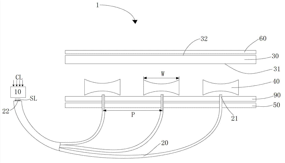
[0022] refer to figure 1 , The direct type backlight module 1 includes an ambient light collection system 10 , several optical fibers 20 , several biconcave lenses 40 , a backplane 50 , a diffusion plate 30 , an optical film 60 and a reflection plate 90 . Wherein, the diffusion plate 30 includes a light incident surface 31, a light exit surface 32 opposite to the light incident surface 31, a reflector 90 arranged under the light incident surface 31, a back plate 50 arranged under the reflector 90, and an optical film 60 It is arranged on the light-emitting surface 32 .

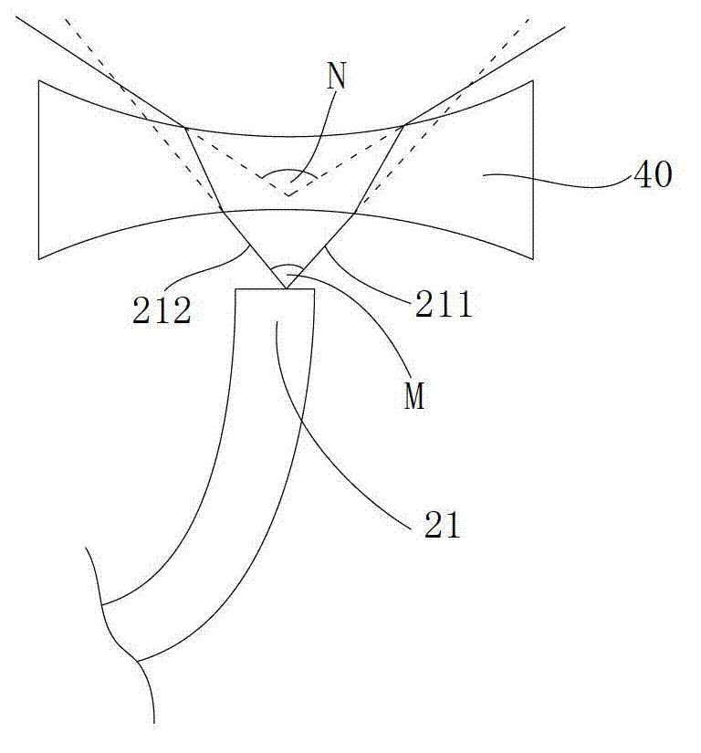
[0023] In this embodiment, the ambient light collection system 10, several optical fibers 20 and several double-concave lenses 40 form a light introduction system, wherein each optical fiber 20 has a light-emitting end 21 and a light-entry end 22, and the entrance of each optical fiber The light ends 22 are converged into a bundle and then adjacent to the ambient light collection system 10 , the light output ...

Embodiment 2

[0034] In the description of Embodiment 2, the same content as in Embodiment 1 will not be repeated here, and only the content that is different from Embodiment 1 will be described below.

[0035] Light-emitting diodes (LEDs), as an original backlight light source commonly used in backlight modules, use electric energy as the power to emit light. Of course, the original backlight light source can also be fluorescent lamps, CCFLs and other illuminants powered by electric energy.

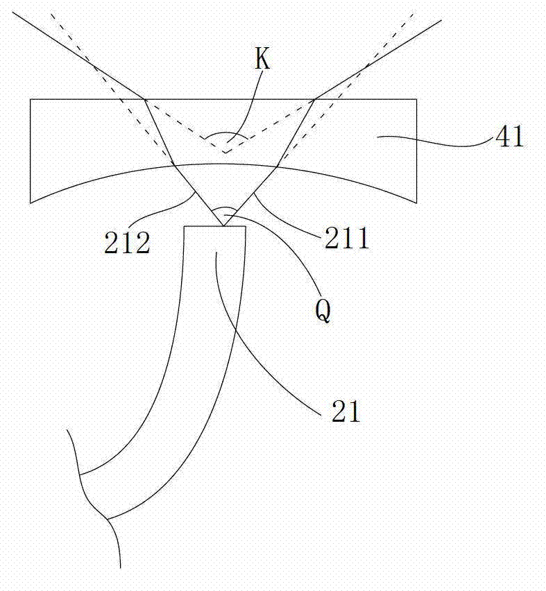
[0036] refer to Figure 5, the direct type backlight module 1 may also include several LEDs 70 , the LEDs 70 and the light outlets 21 are alternately arranged on the reflector 90 , that is, the LEDs 70 and the light outlets 21 are alternately arranged under the light incident surface 31 . A biconcave lens 40 is provided between the light exit end 21 and the light incident side 31 , of course, as mentioned above, the biconcave lens can also be replaced by a plano-concave lens. Through this structure,...


PUM


Abstract

The invention discloses a light guide system, a direct type backlight mould and a liquid crystal display. The light guide system comprises an ambient light acquisition system, multiple light guide devices and multiple diffusing light devices, wherein the ambient light acquisition system faces ambient light and can absorb ambient light and output absorbed light; each light guide device is provided with a light inlet end and a light outlet end, each light inlet end is adjacent to the ambient light acquisition system, absorbed light enters the light inlet end and is guided to the light outlet end, and multiple light outlet end arrays are arranged below an incident surface of a diffusing plate; and each diffusing light device is arranged between the corresponding light outlet end and incident surface, and the diffusing light devices can expand light emitting angles of the light outlet ends. The diffusing light devices arranged between the light outlet ends and the light inlet surfaces can expand the light emitting angles of the light outlet ends, and therefore the nonuniform brightness phenomenon generated among the light outlet ends is improved, and the optical level of a direct type backlight mould is improved.

Description

technical field [0001] The invention relates to the technical field of liquid crystal display, in particular to a light introduction system, a direct-type backlight module and a liquid crystal display. Background technique [0002] Nowadays, most of the backlight modules of LCD (Liquid Crystal Display) use the original light source as the backlight light source. The original light source mentioned here refers to the light source that uses energy such as electricity to make itself emit light, such as LED, CCFL, etc. . Among them, LED has the advantage of high efficiency and energy saving, so it is widely used as a backlight light source in a backlight module. However, as people pay more attention to energy saving and environmental protection in the future, the power consumption of the backlight light source in the current backlight module needs to be further reduced, which requires reducing the number of original light sources used to reduce the power consumption of the back...

Claims


Application Information

Patent Timeline
Patent Type & Authority Applications(China)
IPC IPC(8): F21V8/00F21S19/00G02F1/13357F21Y101/02
CPCG02B6/4298G02B6/0008
Inventor 胡哲彰贺虎
Owner TCL CHINA STAR OPTOELECTRONICS TECH CO LTD
Why Eureka
Try Eureka