Variable scale edge passivation waverider configuration and passivation method

A waveriding configuration and scale-changing technology, applied in the field of hypersonic vehicles, can solve problems such as pressure difference reduction, lift-to-drag ratio reduction, and waveriding configuration lift performance degradation

Active Publication Date: 2016-04-20
NAT UNIV OF DEFENSE TECH
View PDF0 Cites 0 Cited by
  • Summary
  • Abstract
  • Description
  • Claims
  • Application Information

AI Technical Summary

Problems solved by technology

like figure 2 As shown, for the blunt edge waverider configuration, the high-pressure gas that should be confined to the lower surface 2 will leak to the upper surface 1 at the passivated edge 5 in large quantities, resulting in the upper and lower surfaces near the passivated edge 5 The airflow in the air is connected, the pressure difference between the upper and lower surfaces is greatly reduced, and the lift performance of the waverider configuration is significantly reduced.
At the same time, for image 3 In the pointed-edge waverider configuration shown, the attached shock wave in the flow field is replaced by the bow shock wave, and the wave resistance experienced by the aircraft increases significantly
The combined effect of the two factors leads to a sharp drop in the lift-to-drag ratio and a serious loss of aerodynamic performance after the blunt modification of the waverider configuration with sharp edges

Method used


Image

  • Variable scale edge passivation waverider configuration and passivation method
  • Variable scale edge passivation waverider configuration and passivation method
  • Variable scale edge passivation waverider configuration and passivation method

Examples


Embodiment

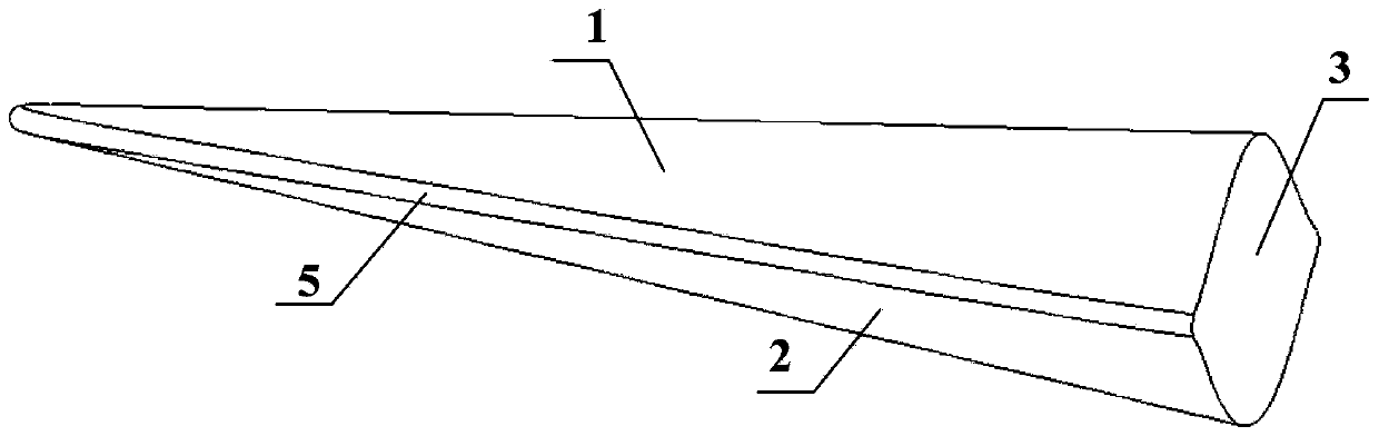
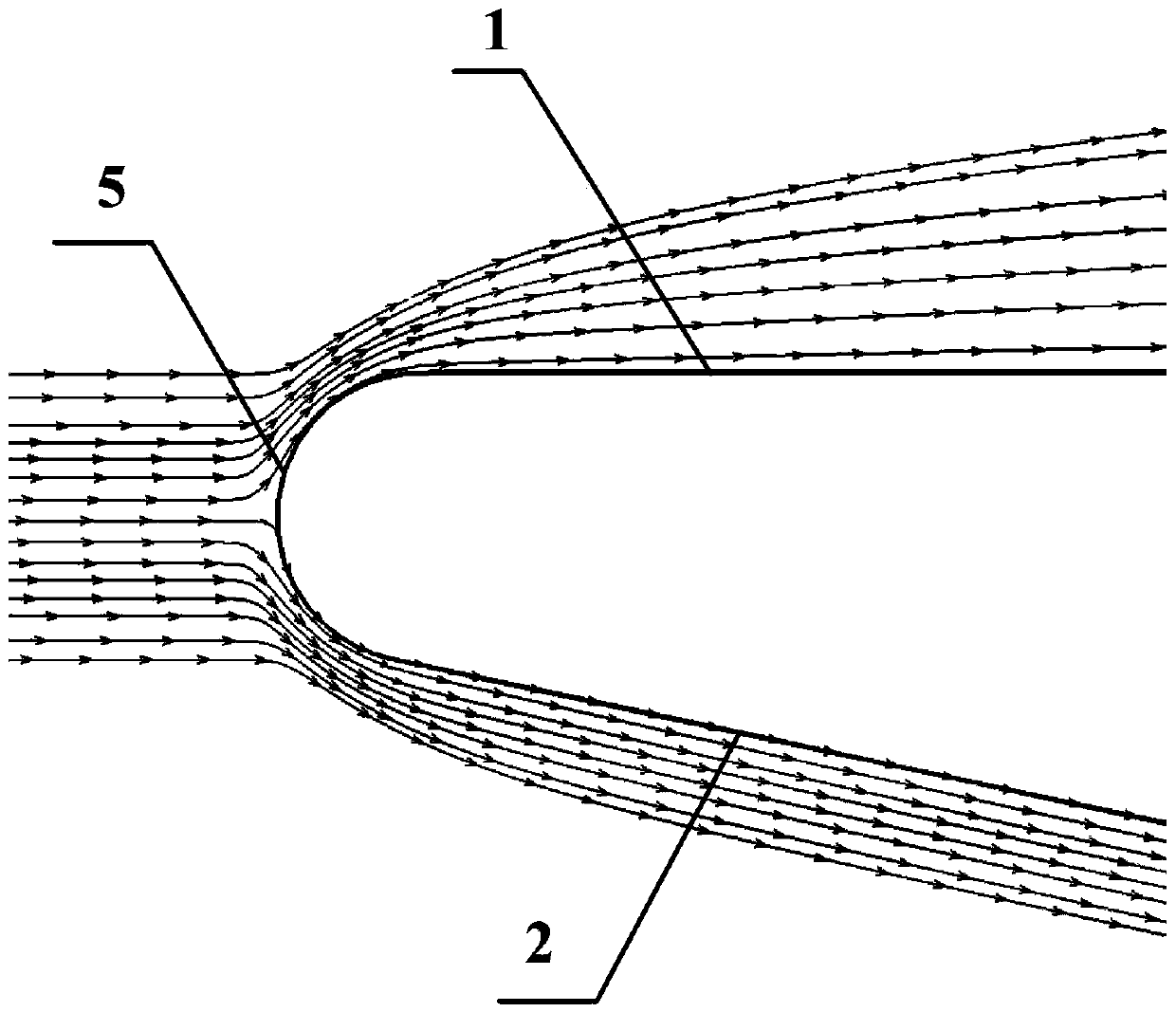
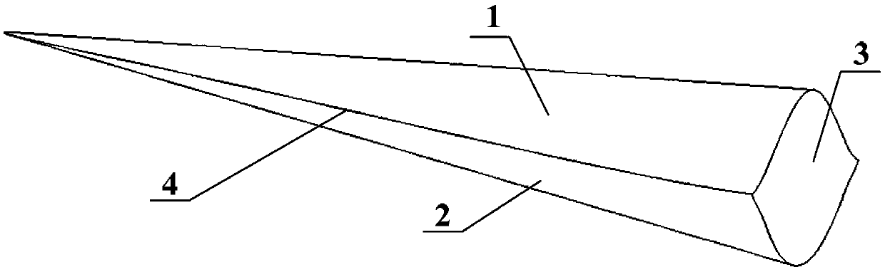
[0038] a kind of like Figure 6 ~ Figure 10 The shown variable-scale edge passivation waverider configuration of the present invention is based on Figure 3 ~ Figure 5 The sharp-edge waverider configuration shown is a passivated precursor, which includes an upper surface 1 and a lower surface 2. The upper surface 1 and lower surface 2 of the sharp-edge waverider configuration intersect to form a sharp-edge waverider type edge line 4; the edge line 4 of the sharp edge waverider configuration includes a stagnation point 7 at the middle position and tail end points 8 at both ends, and the stagnation point 7 is the frontmost point of the tip edge waverider configuration. is the first position to contact the incoming flow; the tail end point 8 is the intersection point of the edge line 4 of the tip-edge waverider configuration and the bottom surface 3 of the sharp-edge waverider configuration; the edge line 4 of the sharp-edge waverider configuration is 7 is divided into a left edge...


PUM


Abstract

The invention discloses a variable scale edge passivation waverider configuration. A sharp edge waverider configuration serves as a passivation precursor. The passivation waverider comprises an upper surface, a lower surface, a bottom surface and a variable scale passivation edge. The variable scale passivation edge is obtained by passivating and modifying an edge line of the sharp edge waverider configuration, the edge line comprises a stagnation point and a tail end point, the passivation radiuses of points on the edge line gradually change from the stagnation point to the tail end point, and the variable scale passivation edge is in symmetric arrangement along the center surface. The invention further discloses a passivation method. The passivation method comprises the steps of first adopting a conventional method to design and make the sharp edge waverider configuration; according to incoming flow conditions, a geometric profile of a stagnation point area and performance parameters of a heat-proof material, designing passivation angles at the position of the stagnation point and performing passivation modification; finally performing passivation modification on other points except the stagnation point, and obtaining the variable scale edge passivation waverider configuration. According to the technical scheme, not only can the heat-proof requirements of the waverider configuration be met, but also aerodynamic performance of the waverider configuration can be improved.

Description

technical field [0001] The invention belongs to the field of hypersonic aircraft, and in particular relates to a waverider configuration and a passivation method for variable-scale edge passivation. Background technique [0002] For conventionally designed hypersonic aircraft, the shock wave breaks away from the edge, causing the high-pressure gas on the lower surface to leak to the upper surface, and the lift performance of the aircraft decreases; at the same time, due to the existence of strong shock waves and boundary layers, the resistance of the aircraft increases; The development of aircraft is facing the problem of "lift-to-drag ratio barrier". [0003] With the deepening of research, the waverider configuration is considered to be an effective attempt to break through the "lift-drag ratio barrier" of hypersonic vehicles. The basic design principle is to confine the high-pressure airflow after the shock wave to the lower surface of the vehicle, without It is allowed ...

Claims


Application Information

Patent Timeline
Patent Type & Authority Patents(China)
IPC IPC(8): G06F17/50
Inventor 侯中喜刘建霞郭正陈小庆杨希祥王鹏韩晶星
Owner NAT UNIV OF DEFENSE TECH
Why Eureka
Try Eureka