Bone conduction receiver with integrated diaphragm

A bone conduction receiver, integrated technology, applied in the direction of diaphragm structure, earpiece/headphone accessories, etc., can solve the problems of loss of harmony of vibration, loss of reliability of the connection between the diaphragm body and bracket, sound quality distortion, etc., to increase the quality, The effect of obvious vibration transmission and clear sound quality

Active Publication Date: 2013-04-17
SUZHOU YICHUAN TECH CO LTD
View PDF3 Cites 8 Cited by
  • Summary
  • Abstract
  • Description
  • Claims
  • Application Information

AI Technical Summary

Problems solved by technology

Since the bone conduction receiver transmits the vibration directly to the auditory ossicles, so that the deaf or the user can hear the sound, the main body of the diaphragm needs to have a large amplitude, but because the amplitude is too large, the connection between the main body of the diaphragm and the bracket is unreliable. Sex, so that the vibration loses harmony and the sound quality is distorted

Method used


Image

  • Bone conduction receiver with integrated diaphragm
  • Bone conduction receiver with integrated diaphragm
  • Bone conduction receiver with integrated diaphragm

Examples


Embodiment 1

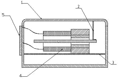
[0028] Such as figure 1 As shown, a bone conduction receiver with an integrated diaphragm includes an electromagnetic shielding shell 1, a diaphragm assembly 3, an electromagnetic conversion device 4 and a microcircuit board 5, and the diaphragm assembly 3 and the electromagnetic conversion device 4 are both arranged on the electromagnetic shielding Inside the shell 1, the electromagnetic conversion device 4 is fixedly bonded to the diaphragm assembly 3, and the electromagnetic conversion device 4 is fixedly connected to the electromagnetic shielding shell 1 through the conductive rod 2; the microcircuit board 5 is fixedly arranged on the outside of the electromagnetic shielding shell 1 and connected 4 electrical connections.

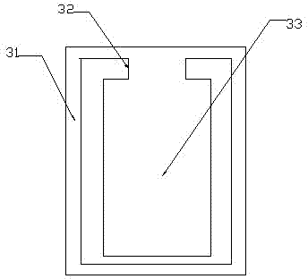
[0029] The diaphragm assembly 3 is integrally formed, including a diaphragm main body 33, a diaphragm support 31 and a connecting portion 32. The diaphragm main body 31 and the diaphragm support 33 are connected as one through the connecting portion 32....

Embodiment 2

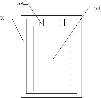
[0035] The rest are the same as in Embodiment 1, the difference is that there are two connecting parts between the diaphragm main body and the diaphragm support, and the width of each connecting part is one-eighth of the width of the diaphragm main body, and the polyurethane film The thickness is 0.02mm.

Embodiment 3

[0037] The rest is the same as that of Embodiment 1, except that there are three connecting parts between the diaphragm main body and the diaphragm holder, and the width of the connecting parts is one-sixth of the width of the diaphragm main body.


PUM


Abstract

The invention discloses a bone conduction receiver with an integrated diaphragm. The bone conduction receiver comprises an electromagnetic shielding shell, a diaphragm component, an electromagnetic conversion device and a micro circuit board, wherein the electromagnetic conversion device is arranged on the diaphragm component and the electromagnetic conversion device and the diaphragm component are both arranged in the electromagnetic shielding shell; the electromagnetic conversion device is connected with the electromagnetic shielding shell through a conduction rod; the micro circuit board is arranged outside the electromagnetic shielding shell and is electrically connected with the electromagnetic conversion device; the diaphragm component comprises a diaphragm main body, a diaphragm bracket and a connection part; the diaphragm main body, the diaphragm bracket and the connection part are integrally formed; the connection part is arranged between the diaphragm main body and the diaphragm bracket; the inner wall of the electromagnetic shielding shell is provided with a stepped surface; and the diaphragm bracket is fixedly arranged on the stepped surface. According to the bone conduction receiver, the diaphragm main body and the diaphragm bracket are combined into an integrated structure, and the shape of the diaphragm main body is improved, so that the amplitude of the diaphragm main body is larger, but the vibration is more stable and regular.

Description

technical field [0001] The invention relates to a bone conduction receiver, in particular to a bone conduction receiver capable of stabilizing and enhancing vibration amplitude. Background technique [0002] In the existing bone conduction receiver, the main body of the diaphragm in the diaphragm assembly and the diaphragm support are split, and one end of the diaphragm is fixed to the diaphragm support by bonding. Since the bone conduction receiver transmits the vibration directly to the auditory ossicles, so that the deaf or the user can hear the sound, the main body of the diaphragm needs to have a large amplitude, but because the amplitude is too large, the connection between the main body of the diaphragm and the bracket is unreliable. Sex, so that the vibration loses harmony and the sound quality is distorted. Contents of the invention [0003] In order to solve the above-mentioned technical problems, the object of the present invention is to provide a bone conducti...

Claims


Application Information

Patent Timeline
Patent Type & Authority Applications(China)
IPC IPC(8): H04R1/10H04R7/02
Inventor 李梁周巍
Owner SUZHOU YICHUAN TECH CO LTD
Why Eureka
Try Eureka