Thin-wall display card type wireless positioning terminal casing

A wireless positioning and terminal housing technology, which is applied to semiconductor devices of light-emitting elements, electrical equipment shells/cabinets/drawers, lighting devices, etc., can solve the problems of increased assembly processes, increased production costs of wireless positioning terminals, and low work efficiency. , to achieve the effect of reducing overall strength, reducing production costs and assembly costs, and reducing design

Inactive Publication Date: 2013-04-17
CHENGDU RUIYI INFORMATION TECH
View PDF5 Cites 0 Cited by
  • Summary
  • Abstract
  • Description
  • Claims
  • Application Information

AI Technical Summary

Problems solved by technology

[0006] In order to display the working status, LED lights are also installed on the circuit board to display the status. Compared with the setting of traditional LED lights, light guide rods are generally used for light guide treatment. Therefore, the production cost of wireless positioning terminals will increase. , at the same time, the assembly process in its production will increase, so it will lead to low work efficiency

Method used


Image

  • Thin-wall display card type wireless positioning terminal casing
  • Thin-wall display card type wireless positioning terminal casing
  • Thin-wall display card type wireless positioning terminal casing

Examples


Embodiment 1

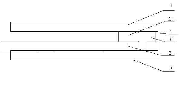
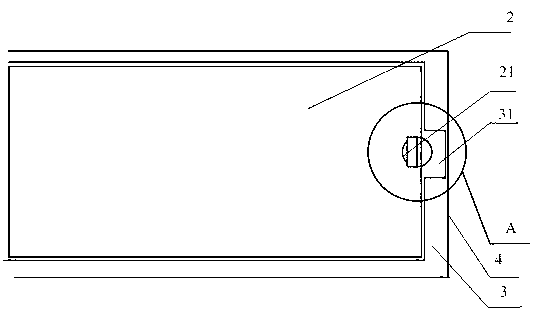
[0025] Such as figure 1 , 2 , 3 shown.

[0026] The thin-walled display card-type wireless positioning terminal housing is mainly composed of an upper cover plate 1, a lower cover plate 3, and a circuit board 2 arranged between the upper cover plate 1 and the lower cover plate 3, and the circuit board 2 is provided with There is an LED lamp 21 , and the upper cover 1 is fastened and connected with the lower cover 3 through the shell wall 4 connected on the plane of the lower cover 3 .

[0027] The LED lamp 21 is arranged near the housing wall 4 .

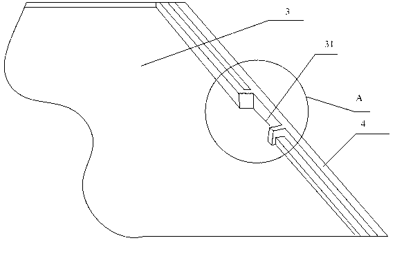
[0028] The lower cover 3 is provided with a thin-walled groove 31 close to the shell wall 4 of the LED lamp 21 , and the lamp cap of the LED lamp 21 is disposed inside the thin-walled groove 31 .

[0029] 4. The thin-wall display card type wireless positioning terminal housing according to claim 3, wherein the groove depth of the thin-wall groove 31 is 10mm.

[0030] The wall thickness of the housing wall 4 of the lower cover pl...

Embodiment 2

[0033] Such as Figure 4 As shown, the difference between the present embodiment and the first embodiment is that a convex lens 5 is embedded inside the thin-walled groove 31 , and the convex lens 5 is arranged between the housing wall 4 and the lamp cap of the LED lamp 21 .

[0034] Due to the influence of the light transmission effect of the housing wall 4 , in view of this technical problem, the present invention also inlays a convex lens 5 inside the thin-walled groove 31 , and the convex lens 5 is arranged between the housing wall 4 and the lamp cap of the LED lamp 21 . In this way, the light emitted by the lamp head of the LED lamp 21 gathers the light at one point through the function of the convex lens 5, and the focal point of the convex lens 5 just hits the housing wall 4, so that the source light brightness of the housing wall 4 increases. And solve the problem of poor light transmission effect of the housing wall 4 .


PUM


Abstract

The invention discloses a thin-wall display card type wireless positioning terminal casing, which mainly consists of an upper cover plate, a lower cover plate and a circuit board, wherein the circuit board is arranged between the upper cover plate and the lower cover plate, an LED (light emitting diode) lamp is arranged on the circuit board, and the upper cover plate is buckled and connected with the lower cover plate through a casing wall connected onto the plane of the lower cover plate. The thin-wall display card type wireless positioning terminal casing has the advantages that 1, the design of light guide posts is reduced, and the production cost and the assembly cost are reduced; 2, after the light guide posts are omitted, the upper cover plate and the lower cover plate can be more tightly matched, and a better sealing effect is realized; and 3, the integral intensity of the thin-wall display card type wireless positioning terminal casing after the assembly can be improved through the reduction of the light guide post matching.

Description

technical field [0001] The invention relates to a wireless positioning terminal, in particular to a thin-wall display card type wireless positioning terminal housing. Background technique [0002] Light-transmitting design of general indicator light: add a light guide column, and transmit the LED light to the outside of the housing through the light guide column. [0003] The light guide column, as the name suggests, is to guide the light inside the machine to display. [0004] The light guide column is mainly divided into the front plate light guide column and the PCB board light guide column. Simply put, one is fixed on the shell of the object, and the PCB board light guide column is fixed on the PCB board. It can guide the signal light emitted by the LED on the PCB board to the panel display through the light guide column, so that it can prevent the danger of static electricity between the circuit board (PCB) board and the shell, and secondly, it can increase the perform...

Claims


Application Information

Patent Timeline
Patent Type & Authority Applications(China)
IPC IPC(8): H05K5/00F21V5/04F21Y101/02F21Y115/10
Inventor 任佳
Owner CHENGDU RUIYI INFORMATION TECH
Why Eureka
Try Eureka