Laser working head with variable width of cladding layer

A technology of laser processing and cladding layer, which is applied in the field of laser processing work heads with real-time variable cladding layer width, can solve the problem of inability to realize real-time change of cladding layer width Problems such as layer width cannot be changed in real time, to achieve real-time change and ensure stability

Inactive Publication Date: 2015-01-07
BEIJING UNIV OF TECH
View PDF4 Cites 0 Cited by
  • Summary
  • Abstract
  • Description
  • Claims
  • Application Information

AI Technical Summary

Problems solved by technology

[0006] The purpose of the present invention is to overcome the shortcomings of the existing synchronous powder feeding cladding method, which cannot realize the real-time matching of the laser defocus amount required for the real-time change of the cladding layer width and the powder delivery position, and solve the problems of existing laser cladding repairs and problems. In laser cladding manufacturing technology, the cladding layer width cannot be changed in real time, and a laser processing working head invented

Method used


Image

  • Laser working head with variable width of cladding layer
  • Laser working head with variable width of cladding layer
  • Laser working head with variable width of cladding layer

Examples


Embodiment approach 1

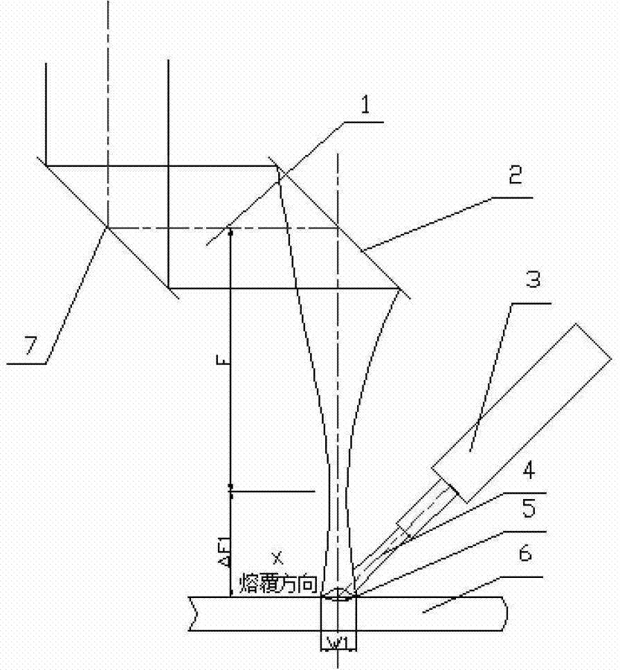
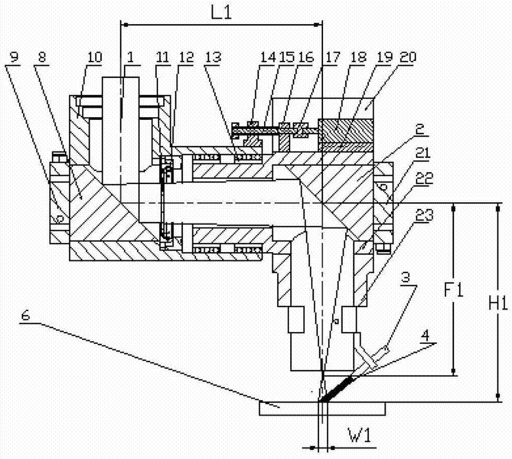
[0038] Figure 3 shows the real-time variable working principle of the cladding layer width in the side-axis powder feeding cladding process using optical fiber transmission for the laser beam.

[0039] These include:

[0040] The optical fiber transmission group includes a transmission optical fiber 27, which is rigidly connected to the collimation unit 26 through a standard QBH interface, and the laser light 1 output by the mirror collimation unit is a near-parallel light.

[0041] The fixed reflector group includes a concave reflector 2, which is installed on the concave reflector mirror base 21 by screws, and the concave reflector mirror base 21 is installed on the concave reflector mounting body 22 by screws;

[0042] The moving reflector group, including the convex reflector 8, is installed on the convex reflector mirror seat 9 by screws, and the convex reflector mirror seat 9 is installed on the convex reflector mounting body 10 by screws;

[0043] The adjustment group in...

Embodiment approach 2

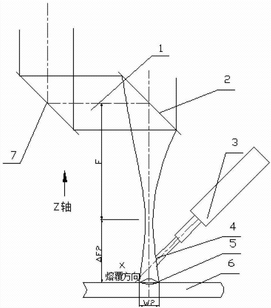
[0059] Fig. 7 is a working principle diagram of the real-time variable cladding layer width in the side-axis powder feeding cladding process where the laser beam is transmitted by the mirror group.

[0060] include:

[0061] The laser beam transmitted by the mirror group can only move the concave mirror due to the existence of the superior reflective transmission mirror, so as to implement the focal length change of the focusing system composed of convex and concave mirrors. The moving mirror groups of mode 2 and mode 1 are different, just opposite. The reflector group includes a concave reflector 2, which is mounted on the concave reflector base 21 by screws, and the convex reflector base 21 is installed on the concave reflector mounting body 22 by screws;

[0062] The fixed reflector group, including the convex reflector 8, is installed on the convex reflector mirror seat 9 by screws, and the convex reflector mirror seat 9 is installed on the convex reflector mounting body ...


PUM


Abstract

The invention discloses a laser working head with variable width of a cladding layer, belonging to the technical field of laser processing. The laser working head comprises a concave reflection mirror assembly, a convex reflection mirror assembly, a protection lens assembly and an adjusting assembly. A focusing system integrated with the working head comprises a convex reflection mirror and a concave reflection mirror; and because of the optimized optical design, the changes of the output focal length of the focusing system is realized by a manner of changing the distance between the two mirrors. Because of the installation of protection lens, partial thermal radiation light can be effectively prevented from entering a laser resonance cavity. For fiber lasers and semiconductor lasers, the stability of output power can be effectively ensured. During the laser cladding process, the working head can realize the real-time changes of the width of the cladding layer.

Description

technical field [0001] The invention relates to a laser processing head whose cladding layer width can be changed in real time, specifically a laser whose cladding layer width can be changed in real time according to the process requirements, which is suitable for laser cladding process and laser forming manufacturing process. The processing head, with its special focus system design, is especially suitable for the application of semiconductor lasers and fiber lasers, and belongs to the field of laser manufacturing technology and equipment. Background technique [0002] Laser cladding process is an advanced surface modification technology. It melts wear-resistant and corrosion-resistant cladding materials on the substrate to be clad by laser irradiation heating, and combines them with the substrate by metallurgical bonding. To achieve the purpose of modifying or repairing the surface of the matrix material. Due to the dense structure of the laser cladding layer, combined wi...

Claims


Application Information

Patent Timeline
Patent Type & Authority Patents(China)
IPC IPC(8): C23C24/10
Inventor 武强肖荣诗吴世凯王旭葆
Owner BEIJING UNIV OF TECH
Why Eureka
Try Eureka