Coaxial powder delivery nozzle applied to variable spot technique

A technology of coaxial powder feeding and variable light spot, which is applied in metal material coating process, manufacturing tools, laser welding equipment, etc., can solve the problems of unusability, achieve the effects of avoiding pollution, reasonable design, and avoiding forming problems

Inactive Publication Date: 2013-04-24
XI AN JIAOTONG UNIV +1
View PDF7 Cites 25 Cited by
  • Summary
  • Abstract
  • Description
  • Claims
  • Application Information

AI Technical Summary

Problems solved by technology

Existing powder feeding nozzles cannot be used for this defocus variable spot forming process

Method used


Image

  • Coaxial powder delivery nozzle applied to variable spot technique
  • Coaxial powder delivery nozzle applied to variable spot technique
  • Coaxial powder delivery nozzle applied to variable spot technique

Examples


Embodiment Construction

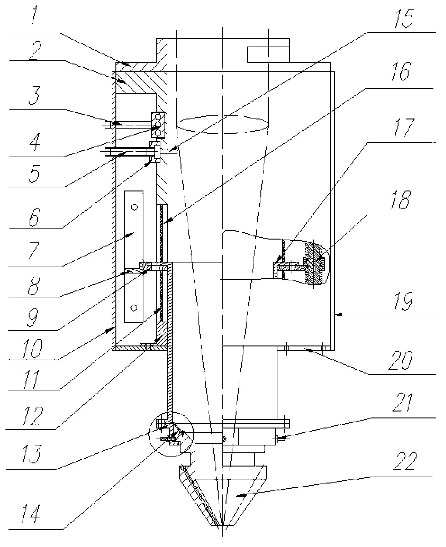
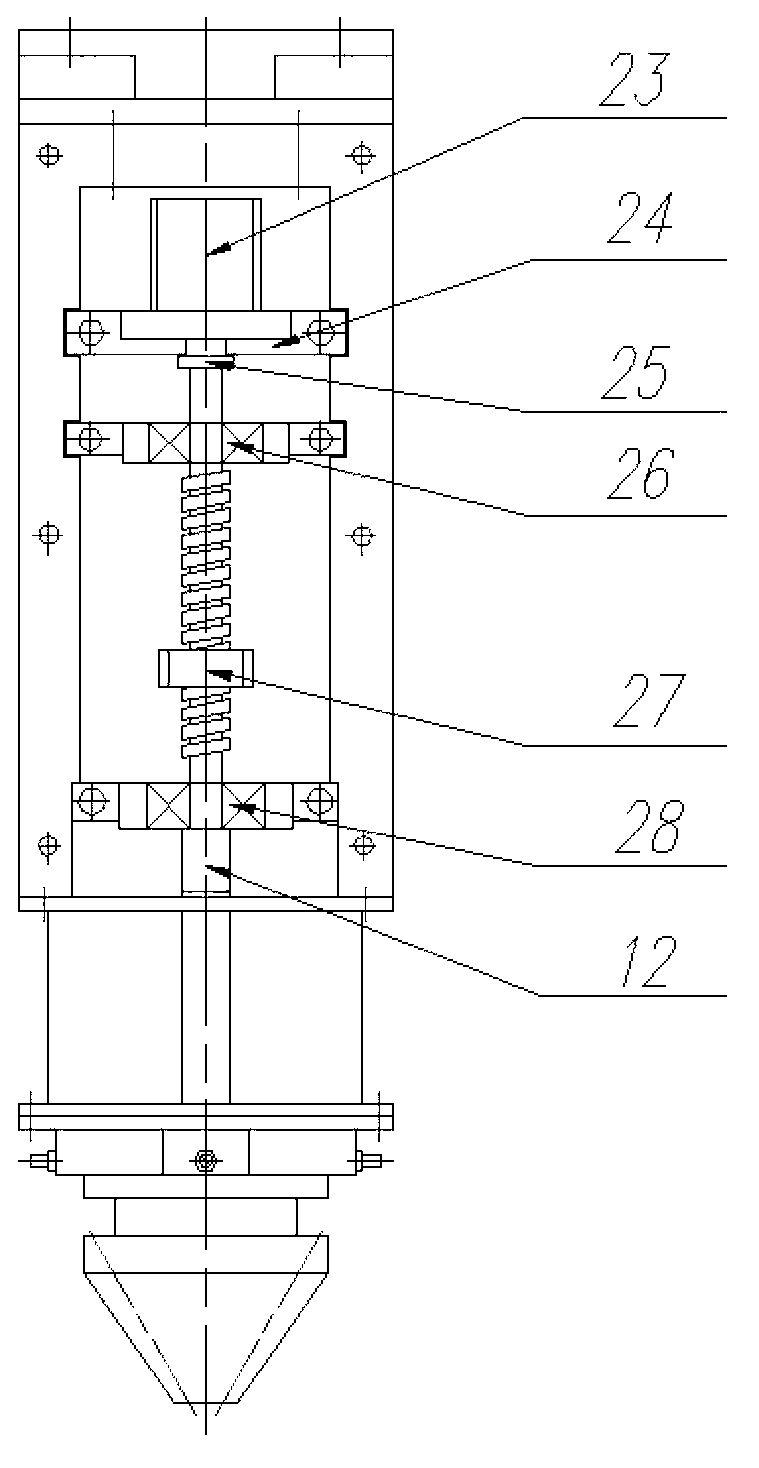
[0024] The present invention consists of three parts, the first part is a structure that automatically adjusts the nozzle powder gathering position in the vertical direction, and this part also includes a cooling water circuit and a gas protection device; the second part is a structure that manually adjusts the powder gathering position in the horizontal diameter direction ; The third part is the powder feeding nozzle structure. Further detailed description will be given below in conjunction with the accompanying drawings.

[0025] refer to Figure 2 ~ Figure 4 , the connecting joint 1 is connected to the laser head (optical fiber, collimator, focusing mirror) on the top, and connected to the shell 2 of the nozzle on the bottom, and axially symmetrical left and right grooves are processed on the shell 2, and on the left A water cooling device and a shielding gas device are provided on the bottom surface of the groove, and the cylindrical through hole in the shell is used as a...


PUM

PropertyMeasurementUnit
widthaaaaaaaaaa

Abstract

The invention relates to a coaxial powder delivery nozzle applied to a variable spot technique. The nozzle consists of three parts, wherein a first part is a structure for automatically regulating the collection position of powder in the nozzle in the vertical direction, and the part further comprises a cooling water loop and a gas protecting device; a second part is a structure for manually regulating the collection position of the powder in the horizontal diameter direction; and a third part is a powder delivery sprayer structure. The coaxial powder delivery nozzle disclosed by the invention is applicable to the field of material increase manufacturing, and especially applicable to an application place adopting a defocusing manner to realize temporary variable spot formation of laser for realizing both formation efficiency and precision. The coaxial powder delivery nozzle disclosed by the invention can also be applied to the field of laser welding.

Description

technical field [0001] The invention relates to a laser metal direct forming device, in particular to a laser metal forming device used for variable spot technology. Background technique [0002] Laser metal forming (also known as laser near-net forming) is a manufacturing technology that uses laser as the processing energy, uses metal powder as the processing raw material, and clads and accumulates layer by layer on the metal substrate to form metal parts. It has developed rapidly in the past ten years. However, a significant disadvantage of this forming method is that the forming efficiency is not high. The main reason is that the movement speed of the equipment along the X and Y directions is not high. At present, the maximum speed of foreign equipment is also below 100mm / s. Some of the problems on it can't even be formed continuously. Efficiency is one of the key indicators of equipment use. At present, the processing strategy of high power and large spot is generally...

Claims


Application Information

Patent Timeline
Patent Type & Authority Applications(China)
IPC IPC(8): C23C24/10B22F3/105B22F7/04B23K26/34B23K26/342
Inventor 李涤尘张安峰侍行坤杨洪涛
Owner XI AN JIAOTONG UNIV
Why Eureka
Try Eureka