Hot air duct for stenter oven

A tenter setting machine and hot air duct technology are applied in the directions of fabric elongation, textile and paper making, fabric surface trimming, etc. to achieve the effects of uniform hot air, smooth surface and energy saving

Active Publication Date: 2015-10-14
无锡市信文机械制造有限公司
View PDF4 Cites 2 Cited by
  • Summary
  • Abstract
  • Description
  • Claims
  • Application Information

AI Technical Summary

Problems solved by technology

To solve the problems existing in the hot air duct of the stenter setting machine oven in the prior art

Method used


Image

  • Hot air duct for stenter oven
  • Hot air duct for stenter oven

Examples


Embodiment Construction

[0015] The technical solutions of the present invention will be further described below in conjunction with the accompanying drawings and through specific implementation methods.

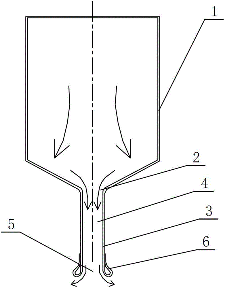
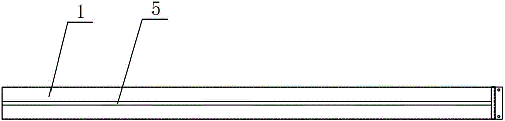
[0016] see figure 1 and figure 2 as shown, figure 1 It is a cross-sectional view of the hot air duct used in the oven of the tenter setting machine provided by Embodiment 1 of the present invention; figure 2 yes figure 1 bottom view.

[0017] In this embodiment, a hot air duct for a stenter setting machine oven includes an air duct body 1, the air duct body 1 is made of galvanized sheet, and its cross-section is a rectangular structure, and the air duct body 1 1 is provided with an air outlet 2 that runs through the entire air duct body 1, and the air outlet 2 extends outwards with a nozzle 3, and the nozzle 3 includes an air uniform channel 4 that is sealed and connected with the air duct body 1, and the air uniform channel The end of 4 is a nozzle opening 5, and the two sides of the end of ...


PUM


Abstract

The invention discloses a hot air duct for a dry oven of a tentering and setting machine. The hot air duct comprises an air duct body, wherein the air duct body is provided with an air outlet running through the whole air duct body, the air outlet extends outwards to form a nozzle, the nozzle comprises a uniform air duct hermetically connected with the air duct body, and the end part of the uniform air duct is provided with a nozzle exit which is in the shape of a circular arc. The hot air duct can utilize hot air more widely, so that gray cloth can receive hot energy more uniformly in larger area, and energy can be effectively saved by about 2%; and meanwhile, hot air blown from the nozzle is more uniform, so that the surface of the grey cloth is more smooth and softer, and the quality of the dried and set grey cloth is improved.

Description

technical field [0001] The invention relates to an oven for a stenter setting machine, in particular to a hot air duct for the oven of a stenter setting machine. Background technique [0002] After the original gray cloth is processed and formed, it must be stretched to become the fabric to be produced. In order to prevent the gray cloth from being torn due to local stress during stretching, it needs to be dipped. Drying and shaping treatment is required. The existing drying and shaping uses a circulating fan to send the hot air heated by the heating device into the drying box to dry and shape the gray cloth through the air duct. The existing air duct is evenly equipped with There are multiple ventilation holes, and the heated hot air passes through the ventilation holes to dry the gray cloth. The design of this structure has the following disadvantages: [0003] 1) The air is not uniform, resulting in uneven surface of the gray cloth; [0004] 2) The design of the ventila...

Claims


Application Information

Patent Timeline
Patent Type & Authority Patents(China)
IPC IPC(8): D06C3/00
Inventor 华文辉
Owner 无锡市信文机械制造有限公司
Why Eureka
Try Eureka