
Automatic compensation device for clutch abrasion for locomotive

An automatic compensation and clutch technology, applied in mechanical drive clutches, clutches, friction clutches, etc., can solve the problems of assembly, complex process, poor automatic compensation effect, and high processing accuracy requirements, and achieve long service life, sensitive response, and low cost. Effect

Active Publication Date: 2013-04-24
WUHU BETHEL AUTOMOTIVE SAFETY SYST
View PDF7 Cites 4 Cited by
  • Summary
  • Abstract
  • Description
  • Claims
  • Application Information

AI Technical Summary

Problems solved by technology

[0012] The technical idea of ​​the present invention is to solve a series of problems in the above-mentioned prior art, such as high requirements for machining accuracy of parts and components, high cost, complex assembly and process, low control precision, and poor automatic compensation effect, in the automatic compensation device for clutch wear. The present invention provides A clutch wear automatic compensation device and a pre-tightening force device are proposed, the mechanism can be automatically adjusted according to the wear amount of the clutch friction plate, so that the clutch friction plate and the flywheel can always be fully combined; the present invention performs wear compensation at the same time , can provide a preload between the release bearing and the diaphragm spring; increase the control accuracy

Method used


Image

  • Automatic compensation device for clutch abrasion for locomotive
  • Automatic compensation device for clutch abrasion for locomotive
  • Automatic compensation device for clutch abrasion for locomotive

Examples


Embodiment Construction

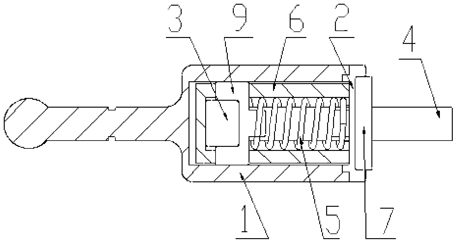
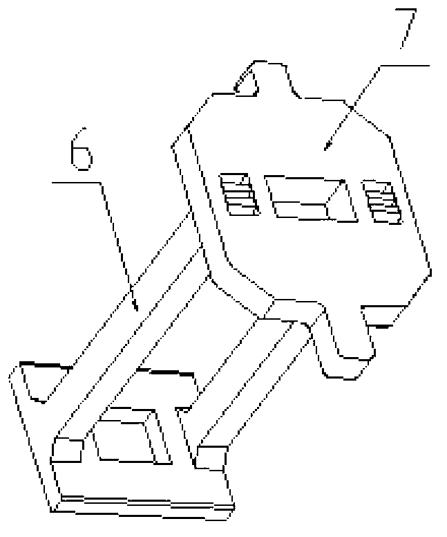
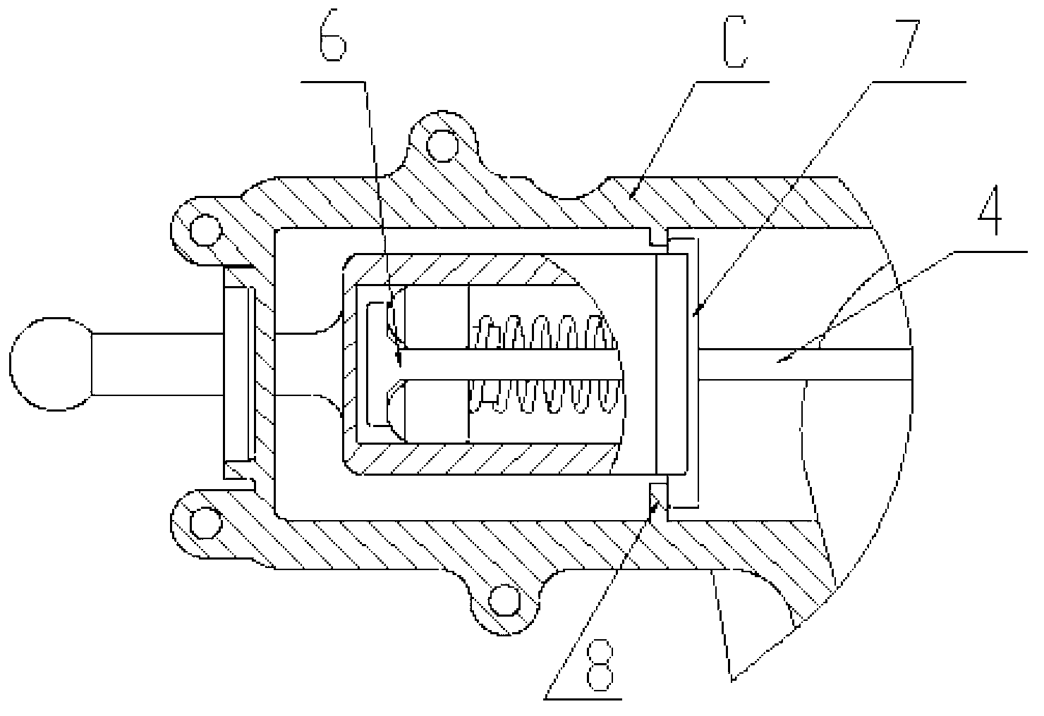
[0027] Referring to accompanying drawings 1 and 2, an automatic clutch wear compensation device of the present invention includes a housing 1, an end cover 2, a roller cage 9, a self-locking roller 3, a pull rod 4, a locking spring 5, a limit plate 6 and a limiter Bit end 7 is composed.

[0028] An automatic compensation device for clutch wear is composed of a casing, an end cover, a locking spring 5 , a self-locking roller 3 , a limiting plate 6 and a pull rod 4 . The shell 1 and the end cover 2 form a closed accommodation space, and the pull rod 4, the roller cage 9, the limit plate 6, the locking spring 5, and the self-locking roller 3 are all contained in the above-mentioned accommodation space.

[0029] When the actuator moves to the initial position, the housing 1 can move freely, and under the action of the diaphragm spring force, the wear of the clutch can be automatically compensated, and a certain pulling force can be output to provide preload for the release bearing...


PUM


Abstract

The invention discloses an automatic compensation device for clutch abrasion for a locomotive. The automatic compensation device is arranged between a clutch separation bearing and a clutch execution mechanism. The automatic compensation device comprises a casing assembly, a self-locking device, a limit device and a pull rod. The self-locking device is arranged in the casing assembly and is a one-way self-locking device. The automatic compensation device achieves abrasion automatic compensation of a clutch under the effect of diaphragm spring piece and outputs certain pull force to provide preload force for the separation bearing. The execution mechanism achieves the automatic compensation function after the clutch is abraded. Simultaneously, preload force for separating a shifting fork and the separation bearing is provided. The automatic compensation device is simple and reasonable in structure, high in control accuracy, sensitive in reaction, stable in manipulation, low in cost and long in service life, has the function of automatic compensation of abrasion, avoids skidding of the clutch and can be widely applied to the locomotive.

Description

technical field [0001] The invention belongs to the technical field of manufacturing parts of the chassis system of a motor vehicle, and in particular relates to an automatic compensation device for clutch wear of a motor vehicle. Background technique [0002] At present, in the technical field of manufacturing components of the chassis system of a motor vehicle, the role of the clutch appears to be particularly important. Generally, the shifting quality of a vehicle transmission depends to a large extent on the control of the clutch. As the clutch wears out, it becomes thinner. At this time, in the initial state, the pressure plate and one end of the diaphragm spring will move towards the direction of the clutch friction plate, while the fulcrum is fixed, so one end of the diaphragm spring will tilt up to act on the release bearing. The release bearing thus exerts a force on the release lever, and one end of the release lever also tilts in the direction of the intermediat...

Claims


Application Information

Patent Timeline
IPC IPC(8): F16D13/75
Inventor 张升张同林季大民刘兆勇李勋
Owner WUHU BETHEL AUTOMOTIVE SAFETY SYST
Learn More