Assisted constant valve

A valve core and valve body technology, applied in the direction of lift valves, valve devices, engine components, etc., can solve the problems of large water impulse, not suitable for large valve applications, and cannot be gradually reduced, so as to achieve the effect of automatic pressure adjustment

Inactive Publication Date: 2013-04-24
SUZHOU YUDONG HVAC TECH CO LTD
View PDF4 Cites 1 Cited by
  • Summary
  • Abstract
  • Description
  • Claims
  • Application Information

AI Technical Summary

Problems solved by technology

[0005] However, when this hydraulic booster valve device is in use, the opening size of the valve cannot be adjusted, and when the valve is closed, it cannot be closed gradually, that is, it cannot be opened and closed gradually. The larger the valve switch, the greater the water impulse, which is not suitable for large-scale Valve application

Method used


Image

  • Assisted constant valve
  • Assisted constant valve
  • Assisted constant valve

Examples


Embodiment Construction

[0042] In the following embodiments, the auxiliary constant valve is opened when the valve stem is rotated counterclockwise as an example for illustration.

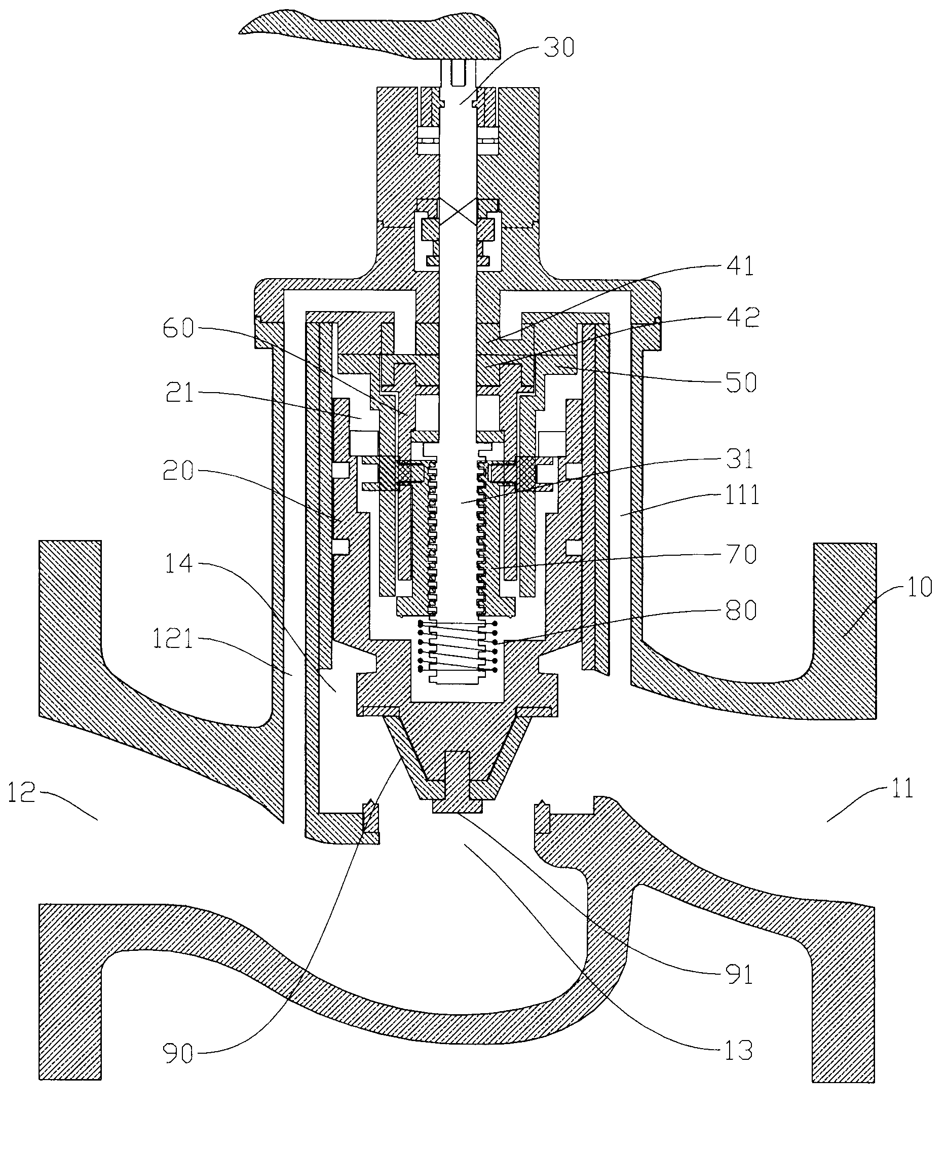
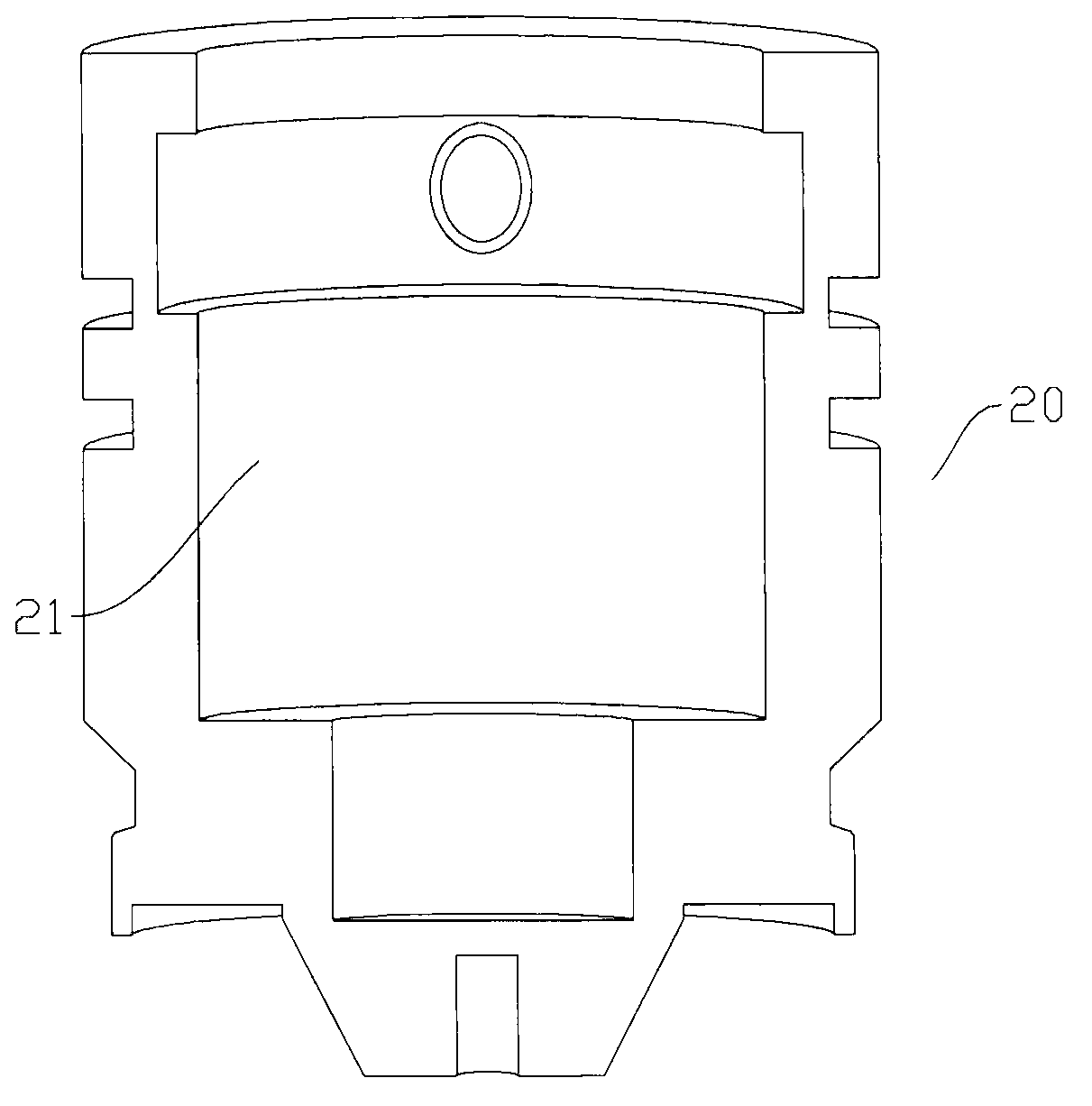
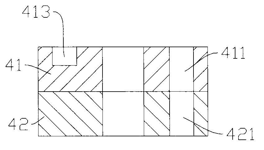
[0043] Examples, see Figure 1 to Figure 8 Shown: auxiliary constant valve, including valve body 10, valve core 20, fixed piece 41, rotating piece 42, valve stem 30 and other components. in:

[0044] The valve body 10 is provided with an inner chamber 14, a first water channel 111, a second water channel 121, and a water inlet 11 and a water outlet 12 connected through the connection port intercepting surface 13, and the lower end of the first water channel 111 communicates with the water inlet 11, A lower end of the second water channel 121 communicates with the water outlet 12 .

[0045] The valve core 20 is located in the inner chamber 14 and the lower part of the valve core 20 is matched with the connection port intercepting surface 13 . That is to say, the lower end of the spool 20 opens or blocks the cut-off surf...


PUM


Abstract

The invention discloses an assisted constant valve which is modified for opening and closing manner and process in valves. Opening or closing is performed according to the change of pressure borne by an inner cavity of a spool, the spool is driven to move up and down in such way that a stem thread is driven by a valve stem to rotate in an internal thread of a moving screw connector, and accordingly the valve can be opened or closed by extremely low power and gradual opening or closing of the valve is achieved then. The assisted constant valve is applicable to large-sized valves.

Description

technical field [0001] The invention relates to the technical field of valves, in particular to an auxiliary constant valve. Background technique [0002] The opening and closing of the valve is mostly adjusted manually (ie, the valve is opened or closed). That is, manpower is required to overcome the torque that the fluid medium brings to the valve stem. For valves with larger specifications, the torque to be overcome is relatively large, so the operation is relatively difficult, and even tools such as wrenches are required. [0003] In view of this, there are valves equipped with electric devices. However, the need to output relatively large torque makes the cost of the electric device extremely high, so it is difficult to promote it vigorously. At the same time, the electric device needs to output relatively large power, so it is easy to be damaged. [0004] Based on the above problems, the applicant has studied a hydraulic booster valve device. The hydraulic booster...

Claims


Application Information

Patent Timeline
Patent Type & Authority Applications(China)
IPC IPC(8): F16K1/02F16K1/32F16K1/52
Inventor 金哲龙
Owner SUZHOU YUDONG HVAC TECH CO LTD
Why Eureka
Try Eureka