
A pneumatic liquid hose valve

A hose valve and liquid technology, which is applied in the direction of diaphragm valves, valve devices, engine components, etc., can solve the problems of solution corrosion, low clamping force, unusability, etc., to achieve improved clamping force, high clamping force, Avoid the effect of channeling

Active Publication Date: 2015-09-02
张琼
View PDF5 Cites 0 Cited by
  • Summary
  • Abstract
  • Description
  • Claims
  • Application Information

AI Technical Summary

Problems solved by technology

[0002] The existing hose valve uses electromagnetic force to clamp the hose, and the clamping force is not high. It cannot be used when it is required to clamp a hose with high elasticity and high hardness. The electromagnetic valve will be in contact with the solution, and it needs to be removed after each use. Cleaning, at the same time, it will be corroded by the solution, etc.

Method used


Image

  • A pneumatic liquid hose valve
  • A pneumatic liquid hose valve
  • A pneumatic liquid hose valve

Examples


Embodiment Construction

[0020] The present invention is described below in the form of specific examples, but the present invention is by no means limited to the following examples.

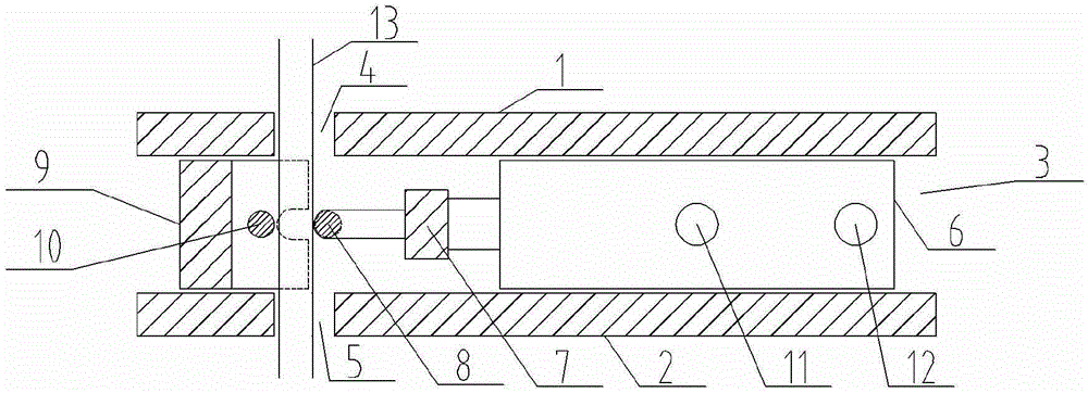
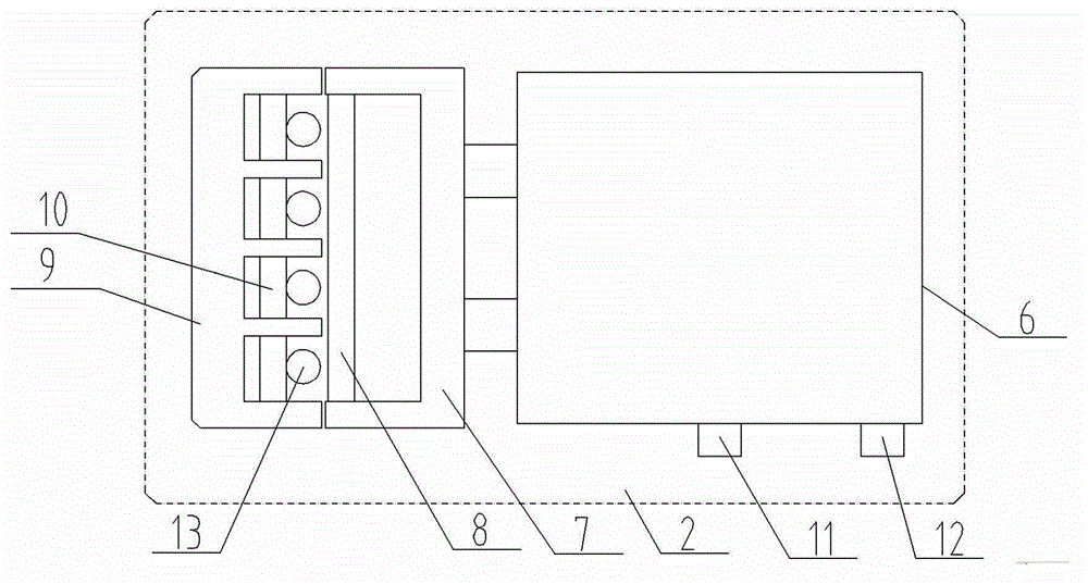
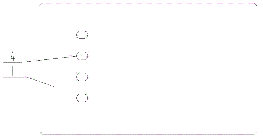
[0021] A pneumatic liquid hose valve such as figure 1 As shown, the pneumatic liquid hose valve includes an upper fixed plate 1, a lower fixed plate 2 and a pinch valve 3 between the upper fixed plate 1 and the lower fixed plate 2, and a hose is inserted into the upper fixed plate 1 Holes 4, hose extension holes 5 on the lower fixed plate 2, one side of the pinch valve 3 includes a cylinder 6, a movable push block 7 connected to the cylinder 6 and a push block connected to the push block 7 The other side of the pinch valve 3 includes a fixed block 9 and a second pinch shaft 10 connected to the block 9 .

[0022] In the original state, there is a space between one side of the pinch valve 3 and the other side, which is greater than the inner diameter of the flexible pipe 13, such as figure 2 As shown, the cylinder 6 us...


PUM


Abstract

The invention provides a pneumatic liquid hose valve which comprises an upper fixed plate, a lower fixed plate and a pinch valve arranged between the upper fixed plate and the lower fixed plate. The upper fixed plate is provided with a hose insertion hole, and the lower fixed plate is provided with a hose extension hole. A cylinder, a movable push block connected to the cylinder and a first clamping pipe shaft connected to the push block are arranged on one side of the pinch valve; and a fixed check block and a second clamping pipe shaft connected to the check block are arranged on the other side of the pinch valve. When used for clamping a hose, the pneumatic liquid hose valve does not contact with solution and cannot be corroded by the solution. The pneumatic liquid hose valve is mainly applied to clamping of the hose high in hardness and high in clamping force, and simultaneously due to the fact that pneumatic thrust is large, multiway hose opening and closing can be achieved.

Description

technical field [0001] The invention belongs to the field of clamping valves, in particular to a pneumatic liquid hose valve. Background technique [0002] The existing hose valve uses electromagnetic force to clamp the hose, and the clamping force is not high. It cannot be used when it is required to clamp a hose with high elasticity and high hardness. The electromagnetic valve will be in contact with the solution, and it needs to be removed after each use. Cleaning, and at the same time, it will be corroded by the solution. Contents of the invention [0003] The invention provides a pneumatic liquid hose valve, which can well solve the above problems. [0004] The invention provides a pneumatic liquid hose valve. The pneumatic liquid hose valve includes an upper fixing plate, a lower fixing plate and a pinch valve between the upper fixing plate and the lower fixing plate. The upper fixing plate has A hose insertion hole, a hose extension hole on the lower fixing plate,...

Claims


Application Information

Patent Timeline
Patent Type & Authority Patents(China)
IPC IPC(8): F16K7/07
Inventor 张琼
Owner 张琼
Learn More