
Flashlight

A flashlight and conductive sleeve technology, applied in the field of flashlights, can solve the problems of expensive metal shells and poor conductivity

Active Publication Date: 2013-04-24
OCEANS KING LIGHTING SCI&TECH CO LTD +1
View PDF2 Cites 2 Cited by
  • Summary
  • Abstract
  • Description
  • Claims
  • Application Information

AI Technical Summary

Problems solved by technology

But because the metal aluminum commonly used in the hand barrel body is easily oxidized in the air, forming an insulating layer, making the conductivity poor, and the metal shell is more expensive

Method used


Image

  • Flashlight
  • Flashlight
  • Flashlight

Examples


Embodiment Construction

[0018] Now carry out further explanation in conjunction with accompanying drawing.

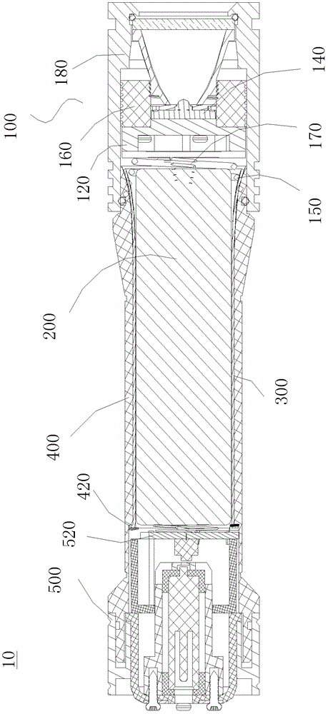
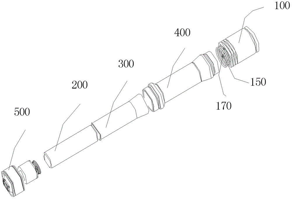
[0019] Such as figure 1 with figure 2 As shown, the flashlight 10 includes a light source part 100 , a conductive sleeve 300 , a barrel body 400 and a tail cap 500 . The light source part 100 and the tail cap 500 are respectively located at two ends of the barrel body 400 , and the conductive sleeve 300 is disposed adjacent to the inner wall of the barrel body 400 .

[0020] The light source part 100 includes a light source circuit board 120 and a light source 140 disposed thereon. The light source 140 is closely surrounded by a cooling frame 160 , the cooling frame 160 is screwed with the lamp head barrel 180 , and the light source circuit board 120 and the light source 140 are fixed in the lamp head barrel 180 , and the lamp head barrel 180 and the barrel body 400 are connected by threads.

[0021] One side of the light source circuit board 120 is provided with a light source 140, and th...


PUM


Abstract

The invention discloses a flashlight which comprises a flashlight body which is made of insulating material. A tail cover and a light source portion are respectively arranged at two ends of the flashlight body. The light source portion comprises a light source circuit board and a light source which is arranged on the light source circuit board. A conductive sleeve is arranged close to the inner wall of the flashlight body. An anode spring is arranged at the center position of one inner side of the light source circuit board facing the flashlight body in a protruding mode. A spiral cathode spring which gradually opens is arranged on the periphery of the anode spring. One end of the cathode spring is connected with the conductive sleeve in a butt joint mode, wherein the diameter of the one end of the cathode spring is longer. The anode spring is communicated with the light source. The tail cover is provided with a tail cover circuit board. A tail cover cathode spring and shrapnel are arranged on the periphery of the end face of the tail cover circuit board facing the light source, wherein the shrapnel is welded on the tail cover circuit board and in electric connection with the tail cover cathode spring. The shrapnel is connected with the conductive sleeve in the butt joint mode. Due to the fact that the conductive sleeve is arranged on the inner wall of the flashlight body, the flashlight has the advantages of reducing cost compared with all-metal construction and preventing return circuit isolation and bad electric conduction from being caused by oxidation of the flashlight body in the air.

Description

【Technical field】 [0001] The invention relates to a lighting device, in particular to a flashlight. 【Background technique】 [0002] Traditional flashlights generally use metal barrels to achieve conductive functions. [0003] The positive and negative poles of the light source are respectively connected to the positive and negative poles of the drive circuit PCB board. The PCB board is fixed on the LED cooling frame. The cooling frame has threads and can be screwed into the lamp holder to fix it. The positive pole of the PCB board is connected to the battery through a spring (or thimble) The positive pole is connected (that is, the positive pole of the battery is turned on and remains connected in both working and non-working states), the negative pole of the PCB board is connected to the LED heat sink, and the negative pole is guided to the lower end of the LED heat sink. The negative pole of the battery is at the tail. It is in contact with the tail cap spring, the tail c...

Claims


Application Information

Patent Timeline
Patent Type & Authority Applications(China)
IPC IPC(8): F21L4/00F21V23/06F21V17/00
Inventor 周明杰黄剑云
Owner OCEANS KING LIGHTING SCI&TECH CO LTD
Learn More