
Hanging-type electric displacement measuring device

An electric displacement and suspension technology, applied in the direction of measuring devices, instruments, etc., can solve the problems of inability to measure the internal displacement of the pile body, the transmission of multi-segment superposition errors, and the inability to recover the fixed instrument, so as to achieve simple and improved displacement measurement work. The effect of repeated service life, reduced difficulty and workload

Active Publication Date: 2014-03-12
SOUTHEAST UNIV
View PDF8 Cites 0 Cited by
  • Summary
  • Abstract
  • Description
  • Claims
  • Application Information

AI Technical Summary

Problems solved by technology

Obviously, due to the inherent characteristics of this method, the displacement of each segment needs to be included in the influence of sensor measurement error, and the transmission of multi-segment superimposed errors is greater; in addition, the process is relatively complicated and the cost of materials is high. Displacement measurement has been improved, but it is rarely used in China, and the traditional one-section rigid rod test method is still used
[0003] Steel wire suspension measurement requires a steel wire to suspend a fixture to the test position, and another steel wire is needed to control the leg extension part of the fixture to fix it with the joint device. Due to the gravity of the fixture and the lowering Deep, the two separated steel wires are easy to be entangled. Once the entanglement occurs, the anchor will be stuck in the protective tube, not only unable to measure the internal displacement of the pile body, which will bring inconvenience to the test, but also the anchor cannot be recycled, causing certain economic losses.

Method used


Image

  • Hanging-type electric displacement measuring device

Examples


Embodiment Construction

[0014] The technical solution of the present invention will be described in detail below in conjunction with the accompanying drawings.

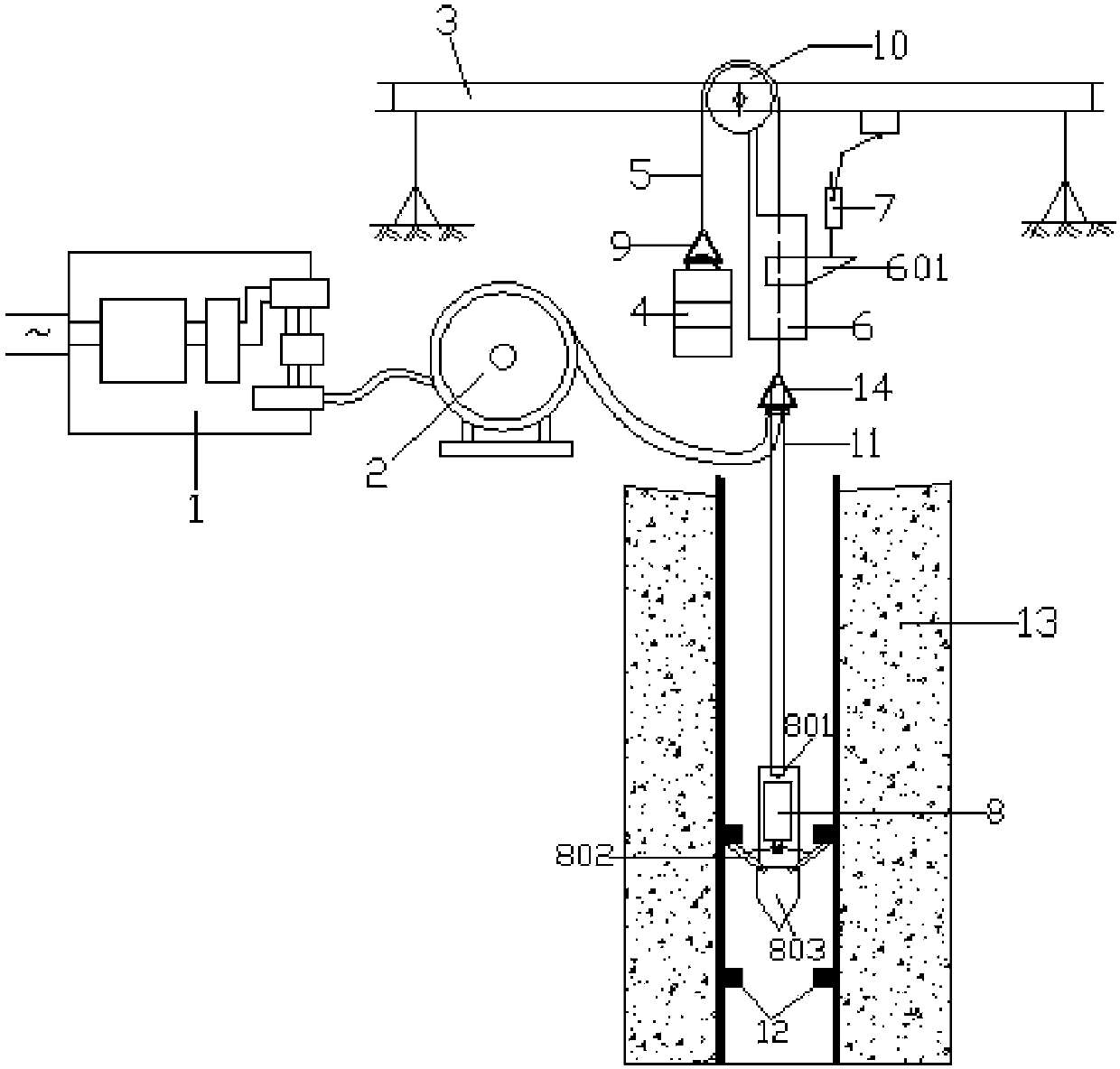
[0015] Such as figure 1 As shown, a suspension type electric displacement measuring device of the present invention includes a power converter 1, a displacement cable reel 2, a reference beam 3, a counterweight 4, a steel strand 5, a sliding meter 6, and a displacement sensor 7 , measuring instrument 8, first safety buckle 9, fixed pulley 10, cable 11 and second safety buckle 14. The power converter 1 is located beside the displacement cable reel 2 . The cable 11 consists of two wires and a steel strand. One end of the cable 11 is wound on the displacement cable reel 2 , and the other end of the cable 11 passes through the second safety buckle 14 and is connected to the tail of the measuring instrument 8 . The fixed pulley 10 is fixedly connected on the reference beam 3 . The steel strand 5 is wound on the fixed pulley 10 . The two ends...


PUM


Abstract

The invention discloses a hanging-type electric displacement measuring device. The hanging-type electric displacement measuring device comprises a power converter, a displacement cable drum, a datum line beam, a weight keeper, a steel strand, a sliding instrument, a displacement sensor, a measuring instrument, a first safety buckle, a fixed pulley, a cable and a second safety buckle. One end of the cable is wound on the displacement cable drum, and the other end of the cable penetrates through the second safety buckle and is connected with the tail portion of the measuring instrument. The fixed pulley is fixedly connected on the datum line beam. The steel strand is wound on the fixed pulley, and two ends of the steel strand are respectively connected with the first safety buckle and the second safety buckle. The first safety buckle is fixedly connected with the weight keeper, and the second safety buckle is fixedly connected with the cable. The sliding instrument is connected on the datum line beam and comprises a sliding block. The surface of the sliding block contacts the displacement sensor. The displacement sensor is connected on the datum line beam. The steel strand penetrates through the sliding block and is fixedly connected with the sliding block. By means of the hanging-type electric displacement measuring device, pile body displacement measuring precision can be improved, steel wire winding can be avoided, and application is safe and reliable.

Description

technical field [0001] The invention belongs to the technical field of displacement measurement devices in pile foundation detection, and in particular relates to a suspension type electric displacement measurement device. Background technique [0002] At present, the internal displacement measurement of the pile body at home and abroad generally adopts two measurement methods: rigid rod and steel wire. The former has been widely used since it was used. It needs to place a rigid rod at the measured displacement of the pile body, extend the rigid rod to the ground, and arrange a displacement sensor on the top of the rod to measure the displacement. However, as the bored piles become longer and even exceed 100m, the inherent defects of this method begin to appear. The rigid rod will bend due to gravity and various other reasons, resulting in obvious distortion in the displacement transmission process. At present, the improvement method in foreign countries is to adopt the rig...

Claims


Application Information

Patent Timeline
Patent Type & Authority Patents(China)
IPC IPC(8): G01B21/02
Inventor 龚维明戴国亮杨超
Owner SOUTHEAST UNIV
Learn More