Adjusting device for verticality and separation distance between shot and imaging chip

A technology of imaging chip and adjustment device, applied in installation, optics, instruments, etc., can solve the problems of affecting imaging effect, inability to adjust the verticality back focal length, etc.

Inactive Publication Date: 2013-04-24
彭中
View PDF5 Cites 12 Cited by
  • Summary
  • Abstract
  • Description
  • Claims
  • Application Information

AI Technical Summary

Problems solved by technology

[0002] Existing digital lenses are widely used in various video imaging systems, and their lenses and PCB boards are often fixedly connected, which makes the verticality between the lens and the imaging chip on the PCB board and the back focal length beyond the lens adjustment range It cannot be adjusted, thus affecting the imaging effect. In view of this, how to improve the existing adjustment device to freely adjust the verticality and spacing between the lens and the imaging chip has become a problem to be solved

Method used


Image

  • Adjusting device for verticality and separation distance between shot and imaging chip
  • Adjusting device for verticality and separation distance between shot and imaging chip
  • Adjusting device for verticality and separation distance between shot and imaging chip

Examples


Embodiment Construction

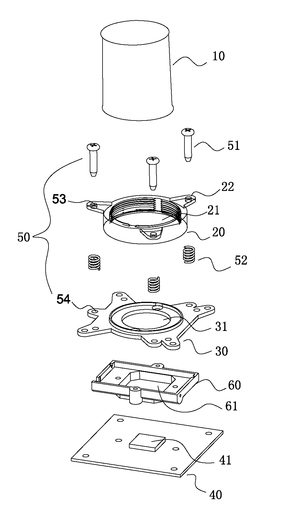
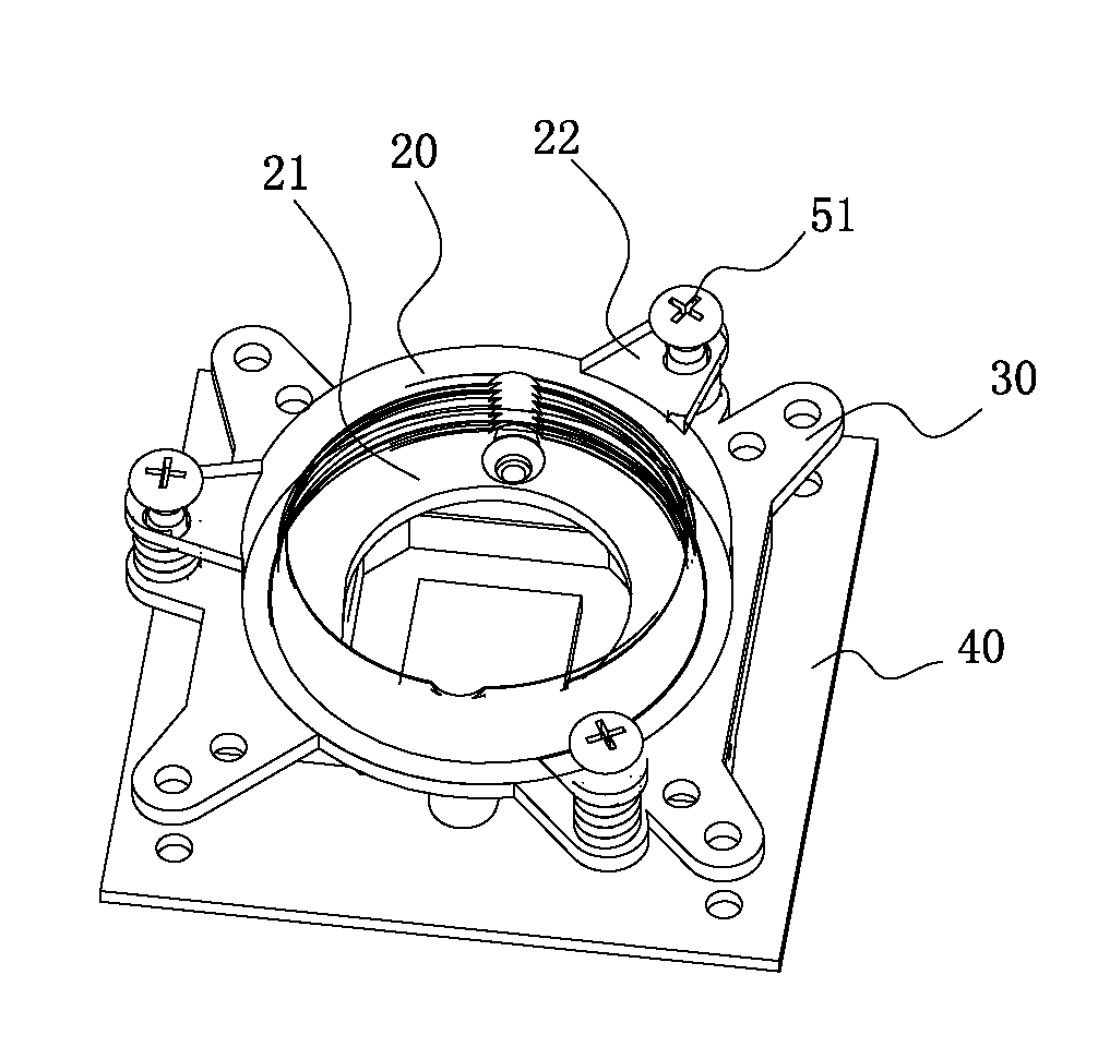
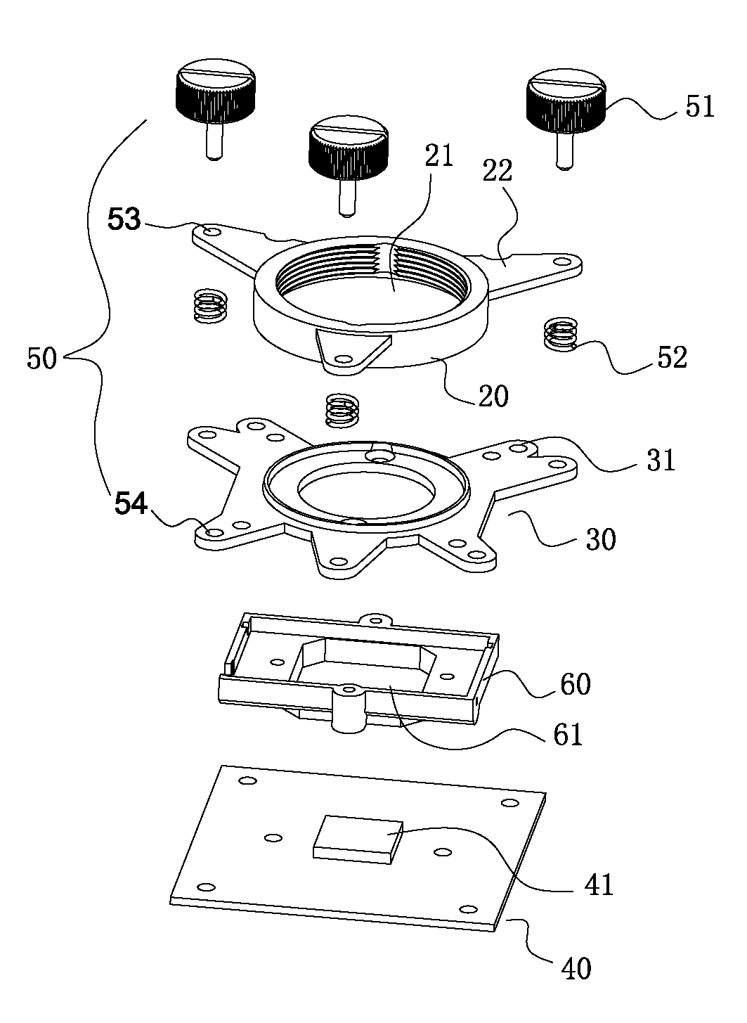
[0026] Such as Figure 1-6 As shown, a device for adjusting the verticality and spacing between the lens and the imaging chip includes a lens 10, a lens holder 20, a lens holder bracket 30 and a PCB board 40 with an imaging chip 41, and the middle of the lens holder 20 is circular Through hole 21, the lens 10 is vertically inserted and fixed on the circular through hole 21 in the middle of the lens holder 20; there is a through hole 31 in the middle of the lens holder bracket 30, and the lens holder bracket 30 and the PCB board 40 with the imaging chip 41 are fixedly connected to form Bracket fixing assembly; the lens holder 20 and the bracket fixing assembly are movably connected by at least three sets of helical elastic adjustment mechanisms 50, and the helical elastic adjustment mechanisms 50 include adjustment screws 51, elastic elements 52, and the first connection hole on the lens holder 20 53 and the second connecting hole 54 on the bracket fixing assembly, any connecti...


PUM


Abstract

The invention relates to an adjusting device for verticality and separation distance between a shot and an imaging chip. The adjusting device for the verticality and the separation distance between the shot and the imaging chip comprises the shot, a shot seat, a shot seat support and a printed circuit board (PCB) with the imaging chip. The shot seat and a support fixing assembly are movably connected through at least three groups of spiral elastic adjusting mechanisms. Each spiral elastic adjusting mechanism comprises an adjusting screw, an elastic element, a first connecting hole in the shot seat and a second connecting hole in the support fixing assembly, wherein one of the first connecting hole in the shot seat and the second connecting hole in the support fixing assembly is an unthreaded hole, the other one is a threaded hole, the adjusting screw penetrates through the unthreaded hole and connected to the threaded hole in a threaded mode, and the elastic element is connected on the corresponding adjusting screw in a sleeved mode and abutted against between the shot seat and the support fixing assembly after pre-compressed in assembly. According to the adjustable mechanism, the verticality and the separation distance between the shot and the PCB with the imaging chip can be adjusted arbitrarily.

Description

technical field [0001] The invention relates to a digital lens adjustment device, in particular to a verticality and distance adjustment device between a lens and an imaging chip. Background technique [0002] Existing digital lenses are widely used in various video imaging systems, and their lenses and PCB boards are often fixedly connected, which makes the verticality between the lens and the imaging chip on the PCB board and the back focal length beyond the lens adjustment range It cannot be adjusted, thereby affecting the imaging effect. In view of this, how to improve the existing adjustment device to freely adjust the verticality and distance between the lens and the imaging chip has become a problem to be solved. Contents of the invention [0003] The object of the present invention is to provide an adjustment device capable of adjusting the verticality and distance between the lens and the imaging chip in 360 degrees in view of the shortcomings of the prior art. ...

Claims


Application Information

Patent Timeline
Patent Type & Authority Applications(China)
IPC IPC(8): G02B7/00
Inventor 彭中
Owner 彭中
Why Eureka
Try Eureka