Probe case protection valve mechanism

A technology of contact box and valve, which is applied to the guard plate/protection device of the switchgear, etc., which can solve problems such as failure of cooperation, difficult balance of torque on the left and right sides, and large resistance to push the protective valve, etc., to achieve safe and reliable operation.

Active Publication Date: 2013-04-24
ANHUI ZHONGDIAN XINGFA & XINLONG TECH CO LTD
View PDF5 Cites 8 Cited by
  • Summary
  • Abstract
  • Description
  • Claims
  • Application Information

AI Technical Summary

Problems solved by technology

When adopting the above transmission design scheme and guiding design scheme, the resistance to push the protective valve is very large and the torque on the left and right sides is not easy to balance, which will cause instability during the movement of the circuit breaker handcart, especially the isolation handcart and voltage transformer handcart. In addition, the stable movement design of the circuit breaker handcart is mostly adopted when the circuit breaker handcart is moved to 80~100mm from the working position, and the positioning pin on the partition plate of the handcart is docked with the positioning hole on the circuit breaker handcart to ensure the circuit breaker. smooth movement and positioning of the
The above design schemes are very likely to cause the failure of cooperation with the protective valve of the contact box during the movement of the circuit breaker handcart, so that the reliable operation of the equipment cannot be carried out.

Method used


Image

  • Probe case protection valve mechanism
  • Probe case protection valve mechanism
  • Probe case protection valve mechanism

Examples


Embodiment Construction

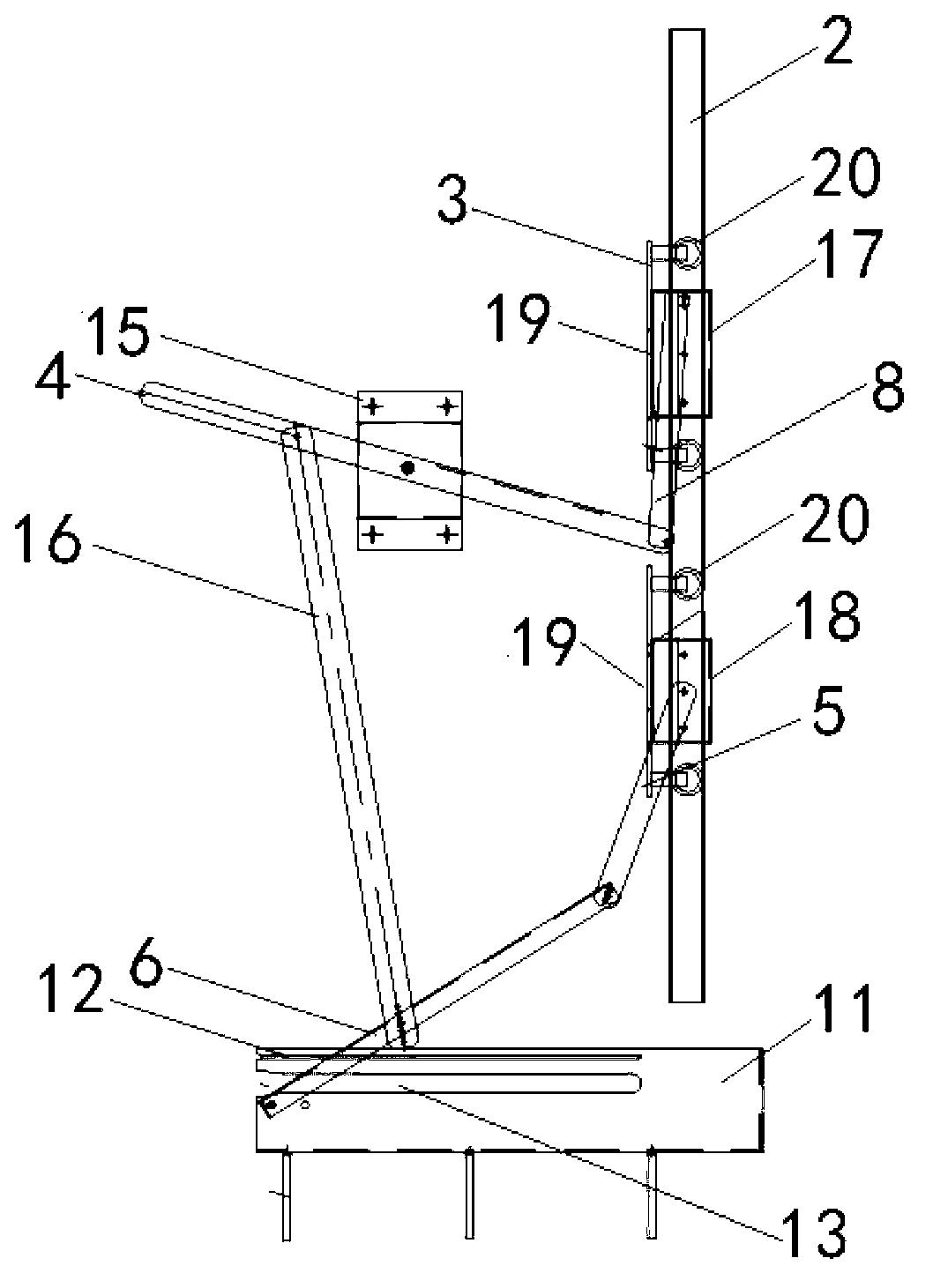
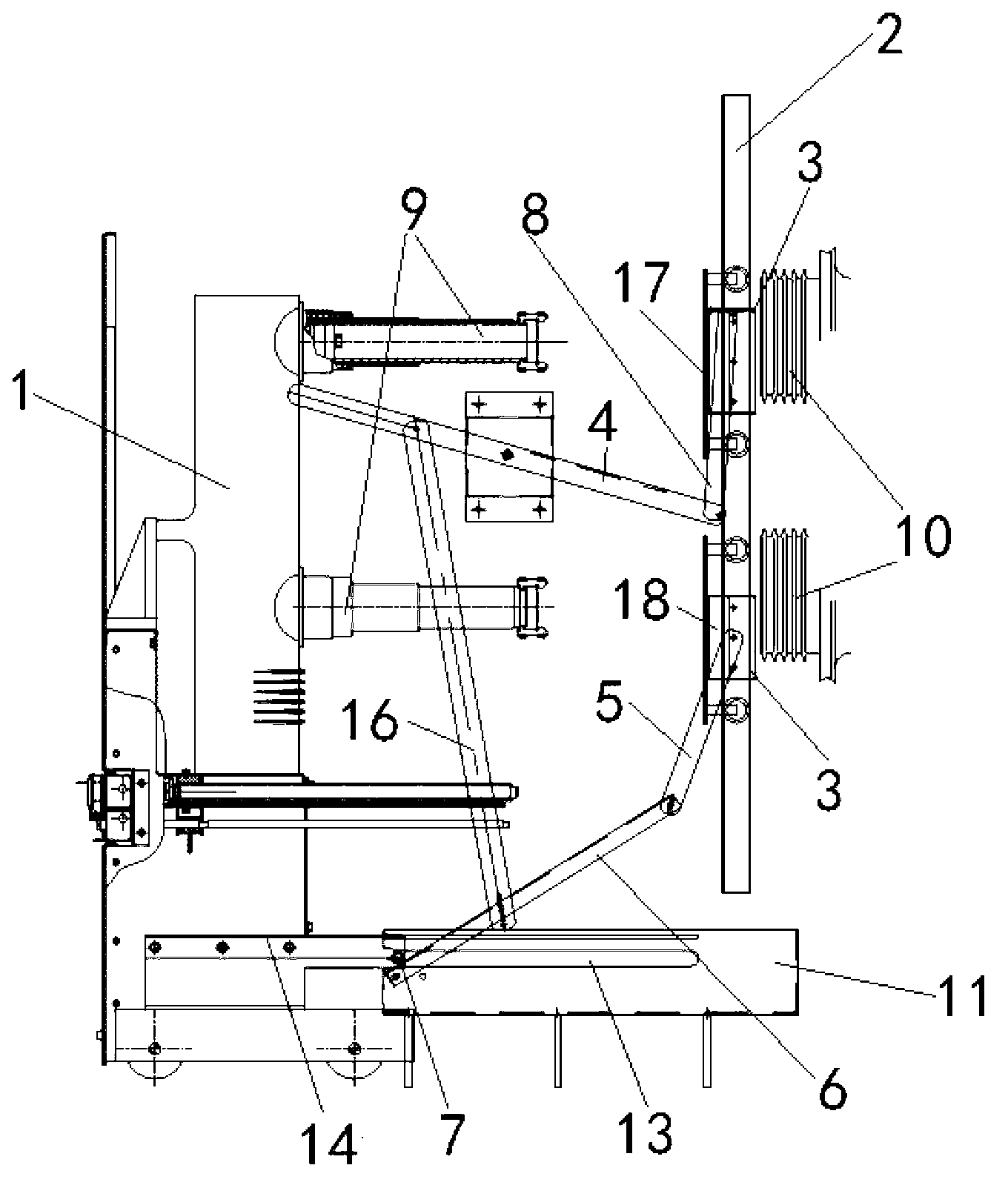
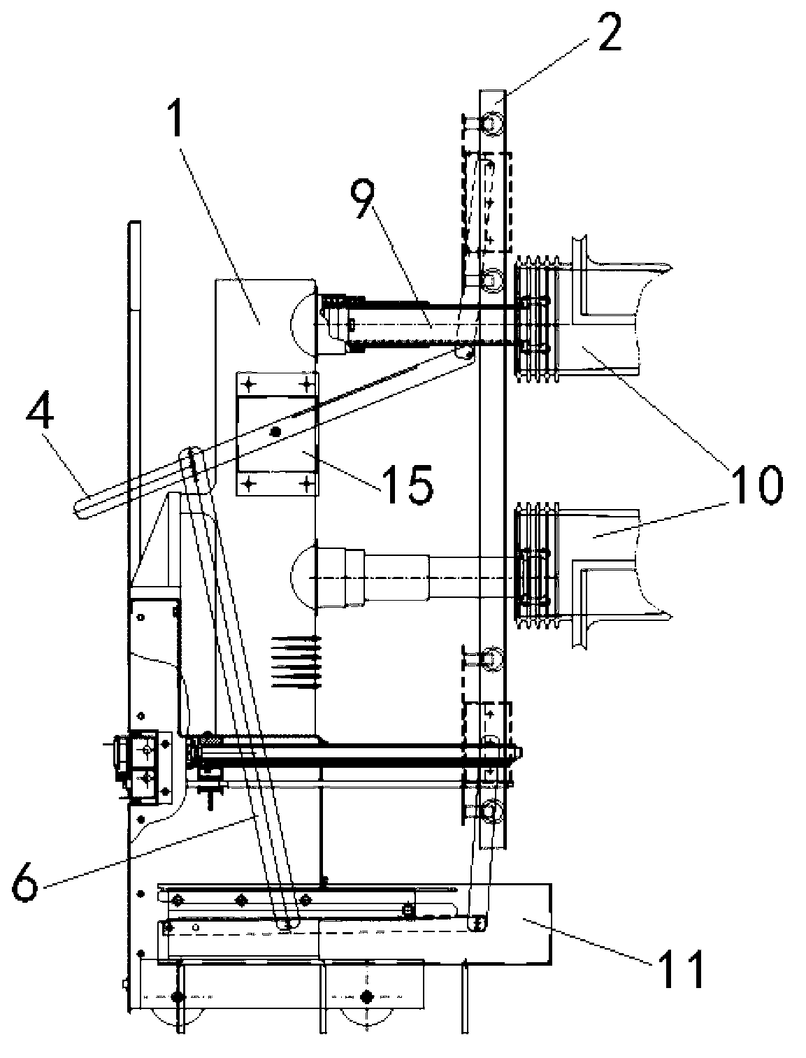
[0018] Below with reference to the accompanying drawings, through the description of the embodiments, the specific embodiments of the present invention, such as the shape, structure, mutual position and connection relationship between the various parts, the role and working principle of the various parts, etc., will be further described. Detailed instructions:

[0019] as attached figure 1 — attached image 3 As shown, the present invention is a contact box protective valve mechanism, including a handcart room, a circuit breaker handcart 1, and the handcart room includes a handcart room rear plate, a handcart room bottom plate and two handcart room side plates. Two rails 2 are installed on the rear panel of the handcart room described above, and two valves 3 that can slide up and down along the two rails 2 are respectively installed in each rail 2, and the two valves 3 in each rail 2 are respectively connected with an upper The valve crank arm 4 is movably connected with a l...


PUM


Abstract

The invention provides a probe case protection valve mechanism. Two valves (3) capable of sliding along two rails are respectively arranged in each rail (2) of the probe case protection valve mechanism, the two valves (3) in each rail (2) are respectively connected with one upper valve connecting lever (4) and one lower valve connecting lever (5), each lower valve connecting lever (5) is connected with one pushing valve connecting lever (6), two upper valve connecting levers (4) are connected with two lower valve connecting levers (5), and the other ends of two pushing valve connecting levers (6) are movably connected with a handcart chamber base plate. A breaker handcart (1) is provided with a valve drive part (7), and when the breaker handcart (1) moves to the handcart chamber direction, the valve drive part (7) is arranged to be a structure capable of pressing the two pushing valve connecting levers (6) to move downwards. The probe case protection valve mechanism can ensure that valves of a probe case protection mechanism can be opened and closed reliably.

Description

technical field [0001] The invention belongs to the technical field of metal armored removable switchgear, and more specifically relates to a protective valve mechanism of a contact box of a switchgear. Background technique [0002] Due to the relatively high voltage level of AC metal armored removable switchgear, the requirements for insulating materials and insulation distance are correspondingly high. The volume and weight of the electrical components used in the equipment are very large and heavy, which affects the safety of the equipment. Operation brings great difficulty. In order to ensure the safe and reliable operation of the equipment, there are more and higher requirements for the design and manufacture of AC metal armored removable switchgear, such as when the circuit breaker handcart is moved from the test position to the working position, the contact box protection The valve of the mechanism can be opened stably and reliably; when it is moved from the working ...

Claims


Application Information

Patent Timeline
Patent Type & Authority Applications(China)
IPC IPC(8): H02B11/24
Inventor 束龙胜李开明诸解平付强周波余浩陶路路
Owner ANHUI ZHONGDIAN XINGFA & XINLONG TECH CO LTD
Why Eureka
Try Eureka