Multi-receiving-end magnetic coupling wireless energy transmission system

A technology of wireless energy transmission and receiving end, which is applied in the direction of electromagnetic wave system, electrical components, circuit devices, etc., and can solve the problems of increased volume and cost

Inactive Publication Date: 2013-04-24
江苏华英光宝科技有限公司
View PDF3 Cites 18 Cited by
  • Summary
  • Abstract
  • Description
  • Claims
  • Application Information

AI Technical Summary

Problems solved by technology

In some occasions (such as multiple implantable external power supply equipment, LED lanterns, etc.), we need to separately provide power for multiple different l...

Method used


Image

  • Multi-receiving-end magnetic coupling wireless energy transmission system
  • Multi-receiving-end magnetic coupling wireless energy transmission system
  • Multi-receiving-end magnetic coupling wireless energy transmission system

Examples


Embodiment Construction

[0025] The following describes the present invention in detail with reference to the drawings and specific embodiments.

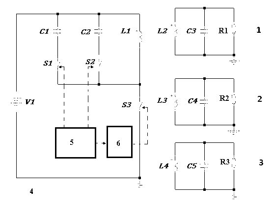
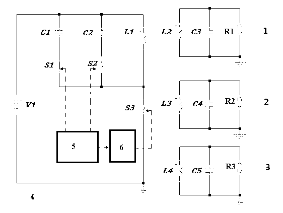
[0026] Reference figure 1 As shown, the multi-receiving end magnetic coupling wireless energy transmission system of the present invention mainly includes: multiple receiving circuits (1, 2, 3), a transmitting circuit 4, a control circuit 5, and a driving circuit 6.

[0027] Each receiving circuit includes: a receiving coil (L2, L3, L4) and a receiving terminal resonant capacitor (C3, C4, C5) and load (R1, R2, R2) connected in parallel with it. As an example, the load (R1, R2) , R2) One end is grounded.

[0028] The transmitting circuit 4 includes an AC power supply V1, a transmitting coil L1, a resonant capacitor branch connected in parallel with a plurality of transmitting coils L1, and a frequency switch S3 driven by the driving circuit 6 connected in series with the transmitting coil L1. The resonant capacitor branch includes a transmitter resonant capacitor ...


PUM


Abstract

The invention discloses a multi-receiving-end magnetic coupling wireless energy transmission system, which comprises a plurality of receiving circuits, a control circuit, a drive circuit controlled by the control circuit and a transmitting circuit, wherein the transmitting circuit comprises a transmitting coil, a plurality of resonant capacitor branches connected in parallel with the transmitting coil, a frequency switch driven by the drive circuit and connected in series with the transmitting coil, and an alternating-current power supply providing electric energy to a circuit formed by connecting the transmitting coil and the frequency switch in series; and each resonant capacitor branch comprises a transmitting end resonant capacitor and a branch switch controlled by the control circuit and connected in series with the transmitting end resonant capacitor. The invention provides the magnetic coupling wireless energy transmission system which can realize the function that a single transmitting end provides electric energy transmission for a designated one in a plurality of receiving ends only by adopting a single transmitting coil. According to the system provided by the invention, wireless power supply to only one receiving end in one state can be achieved under the condition of having the capability of providing wireless electric energy transmission for all the receiving ends, and the system is practical in structure, and easy to implement, and greatly reduces the cost.

Description

Technical field [0001] The invention relates to a wireless energy transmission system, in particular to a multi-receiving end magnetic coupling wireless energy transmission system, belonging to the field of wireless energy transmission. Background technique [0002] Non-radiative magnetic coupling resonance, as a new wireless power supply technology, produces strong mutual coupling by two resonant objects of the same frequency, while only weak coupling to the receiving end of the surrounding non-resonant frequency. The magnetic coupling resonance system includes a transmitting resonance coil, a secondary receiving resonance coil and a load. Assistant Professor Marin Soljacic of MIT is the inventor of the system. His MIT research team demonstrated wireless power supply. They successfully lit a 60W bulb from a distance of 2 meters. Magnetic coupling resonance technology can achieve mid-range energy transmission without increasing the strength of the magnetic field, while tradition...

Claims


Application Information

Patent Timeline
IPC IPC(8): H02J17/00H02J50/12H02J50/40
Inventor 周造辰周岩
Owner 江苏华英光宝科技有限公司
Why Eureka
Try Eureka