Power supply device
A power supply device and power supply technology, applied in the direction of coupling device, circuit, output power conversion device, etc., can solve the problem of taking more space for storage and classification, and achieve the effect of easy storage and easy use
- Summary
- Abstract
- Description
- Claims
- Application Information
AI Technical Summary
Problems solved by technology
Method used
Image

Examples
Embodiment Construction
[0035] A power supply device according to a preferred embodiment of the present invention will be described below with reference to related drawings, wherein the same elements will be described with the same reference symbols.
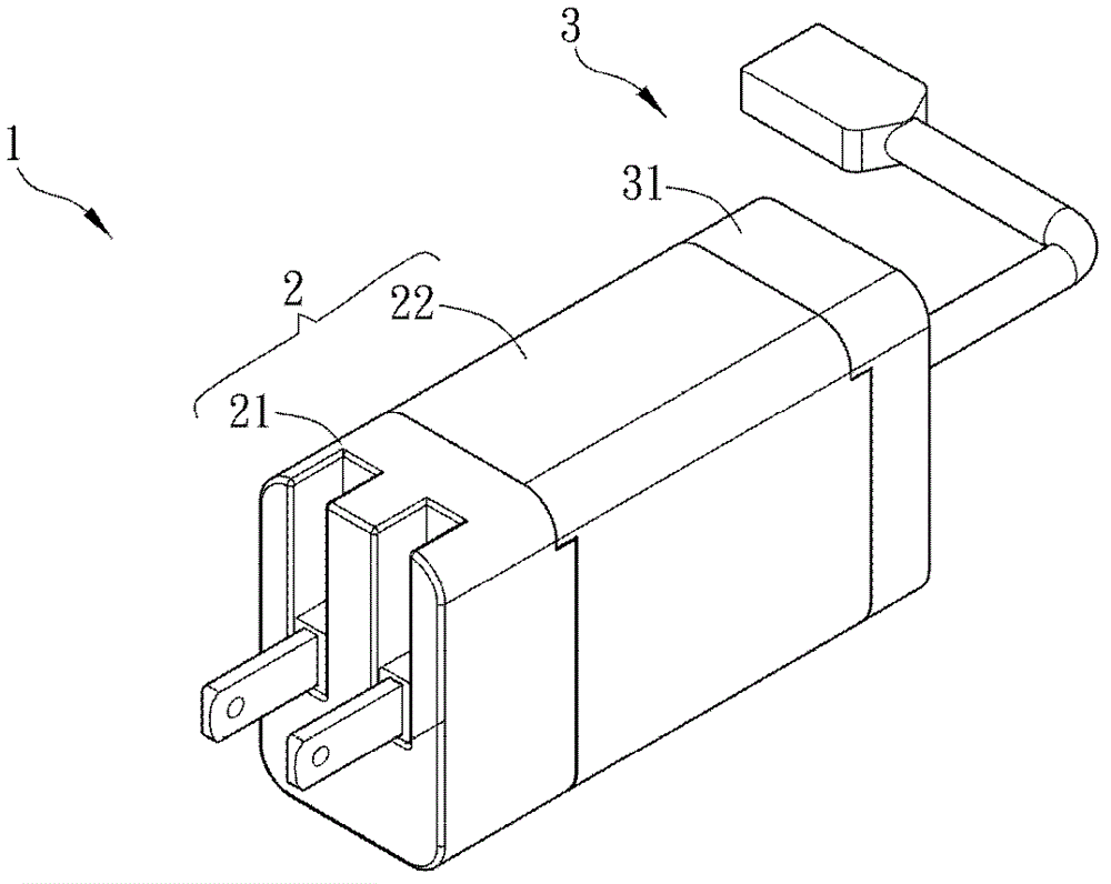
[0036] Please refer to figure 1 Shown is a schematic diagram of a convertible power module 1 according to a preferred embodiment of the present invention. The power supply device 1 includes a power input module 2 and a power function module 3 . The whole power supply device 1 of this embodiment is in the shape of a rectangle. However, the present invention does not limit the shape of the power supply device 1 , which can be made into, for example, cylindrical, square or other shapes, so as to be easy for users to take and use.
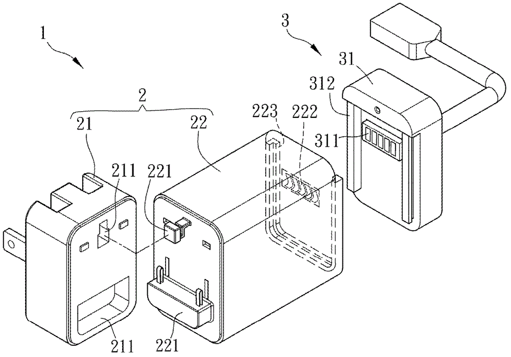
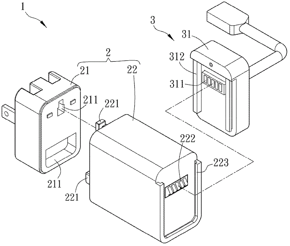
[0037] Please refer to Figure 2 for the figure 1 A schematic diagram of the separation of the power supply device to further illustrate the power supply device 1 of the present invention. The power input module 2 has a powe...
PUM
 Abstract
Description
Claims
Application Information
 - Generate Ideas
- Intellectual Property
- Life Sciences
- Materials
- Tech Scout
- Unparalleled Data Quality
- Higher Quality Content
- 60% Fewer Hallucinations
Browse by: Latest US Patents, China's latest patents, Technical Efficacy Thesaurus, Application Domain, Technology Topic, Popular Technical Reports.
© 2025 PatSnap. All rights reserved.Legal|Privacy policy|Modern Slavery Act Transparency Statement|Sitemap|About US| Contact US: help@patsnap.com