
Device and method for accurately placing thimbles

A thimble and precise technology, applied in the direction of assembling printed circuits with electrical components, can solve the problems of placing large boards for a long time, difficult to ensure smooth tracks, and crushing components

Inactive Publication Date: 2015-08-19
MITAC COMP (SHUN DE) LTD
View PDF2 Cites 0 Cited by
  • Summary
  • Abstract
  • Description
  • Claims
  • Application Information

AI Technical Summary

Problems solved by technology

[0003] In the existing SMT process, when placing the top PIN on the printing machine, the usual practice is that the operator holds the FILM (Film sheet) on the equipment track to measure how to place the top PIN. Because the FILM is plastic and very soft, it is very easy on the track. It is difficult to ensure that it is flat, especially when it takes a long time to place a large board, and it is worried that the top PIN will not be placed correctly and the components will be crushed

Method used


Image

  • Device and method for accurately placing thimbles
  • Device and method for accurately placing thimbles
  • Device and method for accurately placing thimbles

Examples


Embodiment Construction

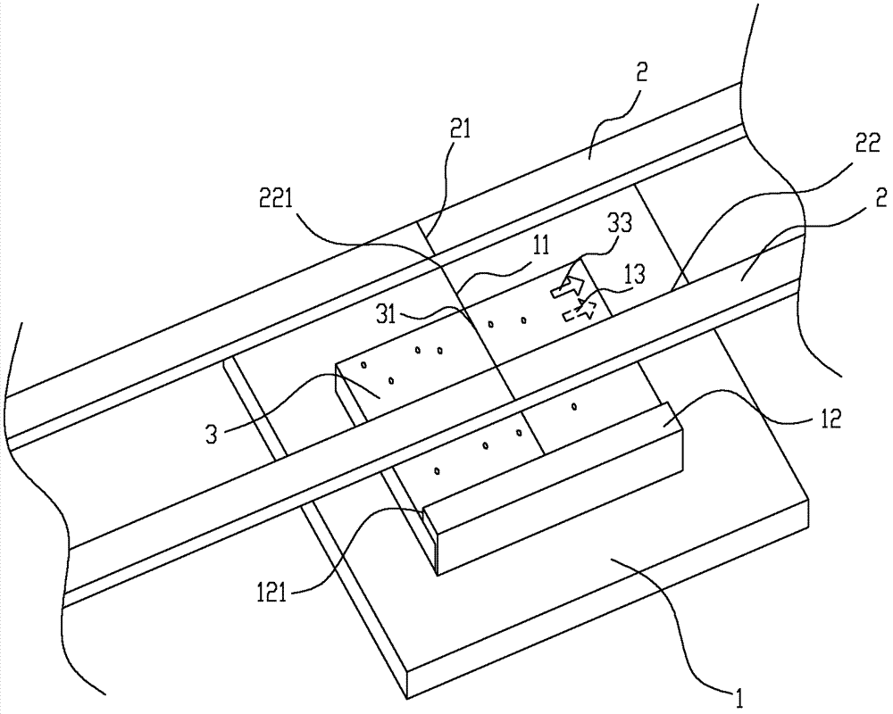
[0023] see figure 1 , there are two rails 2 for transmitting PCB boards on the top of the printing machine platform 1 and near the two sides. The bottom edge on the production surface is aligned with the edge of the inner side 22 of the track 2, so as to avoid the track from covering the surface to be printed. It is worth mentioning that the inner side 22 here refers to the opposite surface of the two tracks. There is a center point 221 corresponding to the center line 21, that is, the center point 221 is located on a line perpendicular to the center line 21 and is aligned with the end points of the center line 21. This center point 221 is a conventional mark on the track, and will not be repeated. . The PCB board is transported on the track through the belt. When the PCB board to be printed reaches the sensor (not shown in the figure) sensing area on the printing machine platform 1, the belt will suspend the transmission, and the PCB board to be printed stops at this time. ...


PUM


Abstract

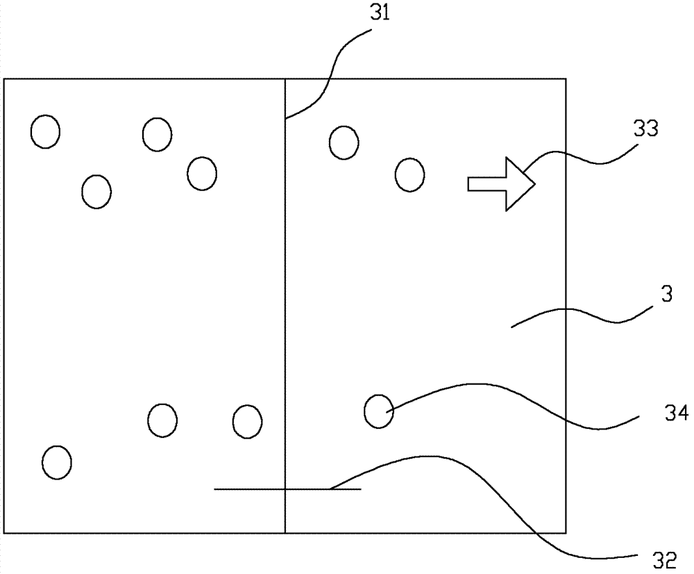
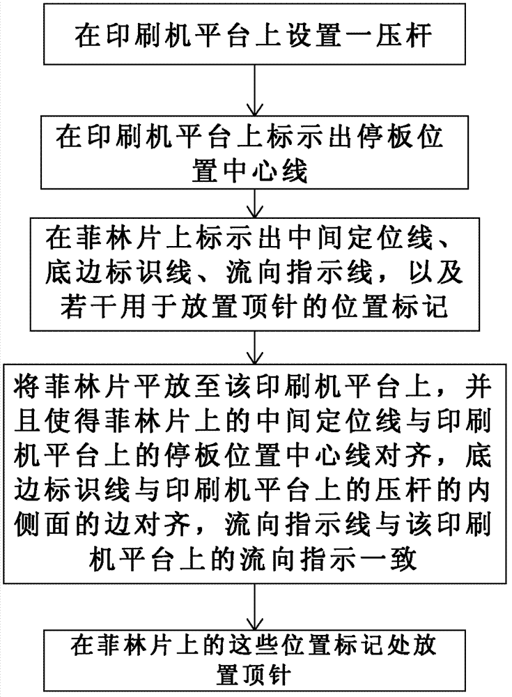
The invention provides a device capable of precisely placing thimbles and a method. The device is applied to a printing machine platform. A rail used for conveying a printed circuit board (PCB) is arranged above the printing machine platform. Due to the fact that a center positioning line on a film is aligned to a center line of a plate stopping position on the printing machine platform, and a bottom marking line on the film is aligned to one side edge of a pressing rod on the printing machine platform. Besides, due to arrangement that a flow direction index line on the film is in accordance with a flow direction indication on the printing machine platform, the film is rapidly and flatly placed on the printing machine platform, then the thimbles are arranged in a plurality of position marks on the film, and therefore fast and precise placement of the thimbles is realized. Besides, the phenomenon that the thimbles damage devices on the PCB is prevented from occurring.

Description

【Technical field】 [0001] The invention relates to the field of circuit board manufacturing, in particular to a device and a method for accurately placing thimbles on a printing machine in an SMT process when manufacturing a circuit board. 【Background technique】 [0002] SMT (Surface Mounting Technology, Surface Mount Technology), mainly uses the placement machine to mount some tiny parts on the PCB board. The production process is: printing solder paste, placement machine placement, reflow oven and Made inspection. In the above-mentioned SMT process (such as printing solder paste, placement machine placement), ejector pins (top pins) are used to fix and support the PCB board. PCB boards are divided into single-sided boards, double-sided boards and multi-layer boards according to the type of layers. For single-sided boards, it is better to place thimbles. The thimbles are adjusted to a uniform height (some machines do not need to be adjusted), and then placed according to th...

Claims


Application Information

Patent Timeline
Patent Type & Authority Patents(China)
IPC IPC(8): H05K3/30
Inventor 李日新
Owner MITAC COMP (SHUN DE) LTD
Learn More