Helical broach

A technology of helical broach and spiral groove, applied in the direction of broach, linear broach, broaching machine, etc., can solve the problems of poor tooth line accuracy, not pulling out at the same time, unstable movement, etc., and achieve the effect of excellent accuracy

Active Publication Date: 2013-04-24
MITSUBISHI MATERIALS CORP
View PDF6 Cites 10 Cited by
  • Summary
  • Abstract
  • Description
  • Claims
  • Application Information

AI Technical Summary

Problems solved by technology

[0007] However, in the final stage of processing, when the helical broach is pulled out from the workpiece, the number of final teeth acting on the workpiece on the circumference of the rear end side of the broach body changes, so the action of the helical broach on the workpiece become unstable
As a result, the workpiece is overcut by finishing the final tooth, and the accuracy of the tooth line deteriorates

Method used


Image

  • Helical broach
  • Helical broach
  • Helical broach

Examples


Embodiment Construction

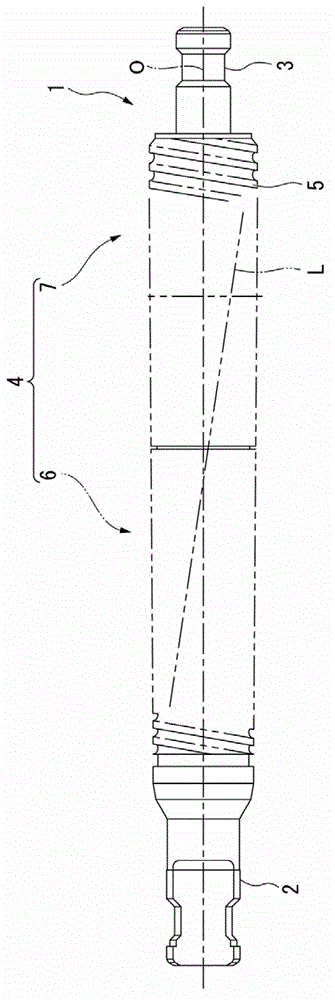
[0040] Figure 1 to Figure 4 An embodiment of the integrated helical broach of the present invention is shown. figure 1 It is a side view showing an embodiment when the present invention is applied to a helical broach. The helical broach of the present embodiment broaches a workpiece in order to manufacture a helical internal gear such as a planetary internal gear having a helical groove on the inner periphery described above, for example. Such as figure 1 As shown, the broach main body 1 is in the shape of a long bar with the axis O as the center. Clamping portions 2 and 3 are formed at both end portions of the broach main body 1 . A cutting tooth portion 4 is formed between the clamping portions 2 , 3 . In this cutting tooth portion 4, a plurality of cutting teeth 5 protruding radially outward from the outer circumference of the broach main body 1 are formed from the front end side of the broach main body 1 ( figure 1 on the left side) to the rear end side ( figure 1 T...


PUM


Abstract

This helical broach forms a twisted groove at the inner periphery of a machined hole of a work by means of a plurality of cutting blades. The plurality of cutting blades have: a plurality of groove depth-expanding blades that are arrayed towards the tip of a broach body; and a plurality of groove width-expanding blades that are arrayed towards the base of the broach body. The plurality of groove width-expanding blades have a cutting blade and a guiding blade. The groove width-expanding blade positioned furthest towards the base of the broach body is formed with a guiding blade instead of a cutting blade at the edge of intersection of a scooping surface and the lateral surface that faces one of the wall surfaces from among both groove wall surfaces of the twisted groove of the work.

Description

technical field [0001] The present invention relates to a helical broach used for cutting a workpiece, for example, when manufacturing a helical internal gear having a helical groove on the inner periphery. [0002] this application claims priority based on Japanese Patent Application No. 2010-191074 for which it applied to Japan on August 27, 2010, and uses the content. Background technique [0003] An example of a helical internal gear is a planetary internal gear. Various planetary internal gears are offered as gears for automatic transmissions. However, with recent high-quality automatic transmissions, high-quality gears are also required. [0004] Helical broaches are used in the machining of such helical internal gears. For example, the following Patent Document 1 proposes a helical broach in which a plurality of cutting teeth (cutting teeth) protruding toward the radially outer peripheral side of the broach main body extend from the outer peripheral portion of the ...

Claims


Application Information

Patent Timeline
IPC IPC(8): B23D43/02B23F21/26
CPCB23D43/005B23F21/26Y10T407/16B23D43/02
Inventor 善积直树小林好夫河野贤祐藤原秀之
Owner MITSUBISHI MATERIALS CORP
Why Eureka
Try Eureka