Reciprocating fine blanking compound die

A mold and precision technology, applied in the field of compound molds for blanking process and reciprocating precision compound blanking molds, can solve the problems of reducing the service life of molds, increasing production costs, aggravating cutting edge wear, etc., to improve work efficiency and reduce production. cost, reduce the effect of subsequent processing

Inactive Publication Date: 2013-05-01
CHANGZHI HUIFENG ELECTROMECHANICAL INDAL TRADE
View PDF10 Cites 6 Cited by
  • Summary
  • Abstract
  • Description
  • Claims
  • Application Information

AI Technical Summary

Problems solved by technology

[0002] At present, there are two types of blanking processes used at home and abroad: one is ordinary blanking, and the other is precision blanking. There are burrs on the surface. The burrs not only affect the appearance of the parts, but also easily cause cracks due to stress concentration in the subsequent deformation process.
The height of the burr mainly depends on the strength of the material to be punched, the thickness of the material, the size of the blanking gap and the wear of the die edge, etc. Although the improvement of the above factors can limit the height of the burr to a certain minimum value, after the improvement The burrs still cannot meet the punching parts with high requirements for shape and dimensional accuracy, and subsequent processing is required to reduce or eliminate burrs
This brings more production costs, and the production efficiency is not high

Method used


Image

  • Reciprocating fine blanking compound die

Examples


Embodiment Construction

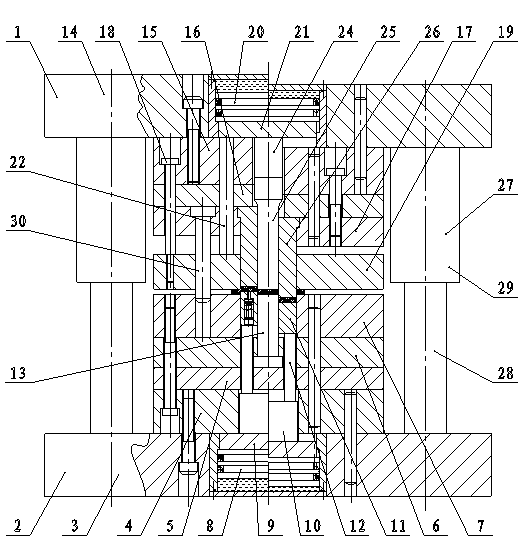
[0016] Such as figure 1 As shown, the reciprocating precision composite blanking die of the present invention includes an upper die 1 and a lower die 2, and the structure of the lower die 2 is: the lower die base 3 is superimposed and fixed with a lower template 4, a lower die base 3 from bottom to top through bolts. The backing plate 5, the lower fixing plate 6 and the lower die 7, the center of the lower mold base 3 and the lower template 4 are all provided with through holes, and the lower oil cylinder 8 is installed in the center hole of the lower mold base 3, and the lower oil cylinder 8 A lower pressure bearing plate 9 is fixed on the piston, a lower pressure block 10 is fixed on the lower pressure bearing plate 9 and the lower pressure block 10 is movably fitted in the center hole of the lower template 4, and the center of the lower die 7 is also provided with a Through holes, the lower convex and concave molds 11 are movably fitted in the center hole of the lower conca...


PUM


Abstract

The invention relates to a reciprocating fine blanking compound die, which belongs to the technical field of dies and aims to solve the technical problem to provide a fine blanking compound die which is capable of reducing blank burrs. The reciprocating fine blanking compound die has the technical scheme that the die comprises an upper die and a lower die, wherein the lower die has the structure that a lower die plate, a lower base plate, a lower fixing plate and a lower concave die are sequentially fixed on a lower die seat through bolts, and a lower oil cylinder is arranged in a central hole 6+5 of the lower die seat, a lower pressure bearing plate is fixed on a piston of the lower oil cylinder, and lower convex and concave die is sleeved in a central hole of the lower concave die; and the upper die has the structure that an upper die plate, an upper base plate and an upper fixing plate are sequentially fixed on the bottom of an upper die seat through bolts, bolts of an upper concave die are connected with the upper concave die after penetrating through the upper die plate, the upper base plate and the upper fixing plate, an upper oil cylinder is arranged in a central hole of the upper die seat, the upper part of an upper convex die is movably sleeved in a central hole of the upper base plate, and the lower part of the upper convex die is sleeved in a central through hole of an upper convex and concave die. According to the blanking die disclosed by the invention, raw materials are blanked bidirectionally to effectively reduce the burrs.

Description

technical field [0001] The invention relates to a reciprocating precision composite blanking die, which belongs to the technical field of dies, and in particular relates to a composite die for blanking technology. Background technique [0002] At present, there are two types of blanking processes used at home and abroad: one is ordinary blanking, and the other is precision blanking. There are burrs on the surface. The burrs not only affect the appearance of the parts, but also easily cause cracks due to stress concentration in the subsequent deformation process. . The height of the burr mainly depends on the strength of the material to be punched, the thickness of the material, the size of the blanking gap and the wear of the die edge, etc. The improvement of the above factors can limit the height of the burr to a certain minimum value, but after the improvement The burrs still cannot meet the punching parts with high requirements for shape and dimensional accuracy, and su...

Claims


Application Information

Patent Timeline
Patent Type & Authority Applications(China)
IPC IPC(8): B21D28/14B26F1/44
Inventor 李春庄牛福忙杨跃平石青亮
Owner CHANGZHI HUIFENG ELECTROMECHANICAL INDAL TRADE
Why Eureka
Try Eureka