New energy automobile motor V-shaped mounting adjustment device

A new energy vehicle, installation and adjustment technology, applied in the direction of motor vehicles, transportation and packaging, etc., can solve the problems of increased workload, inaccurate control, self-heavy motor, etc., to reduce the input of manpower and material resources, and accurately control the tilt angle , the effect of reducing the number of adjustments

Inactive Publication Date: 2013-05-01
JIANGXI B ENERGY SHANGRAO COACH
View PDF5 Cites 5 Cited by
  • Summary
  • Abstract
  • Description
  • Claims
  • Application Information

AI Technical Summary

Problems solved by technology

The problems that arise during this installation process are: first, the motor has a large dead weight, and the inclination angle on the vehicle cannot be accurately controlled; second, although the motor is fixed by a square bar and no longer rolls over, it cannot be adjusted when the forklift moves and adjusts. In the process, the square bar will move, causing the motor to deviate from the original fixed position. It needs to be adjusted several times to complete the adjustment work, which increases the actual workload.
[0003] Therefore, in view of the limitations, instability, and unsafe shortcomings of the above-mentioned traditional installation methods for new energy vehicle drive motors and ISG motors, it is necessary to provide a new energy vehicle motor installation adjustment device, which can be suitable for installation of various types and sizes of motors. Accurately control the tilt angle of the motor, the installation is stable and safe, accurate and simple, greatly simplify the installation process, reduce the input of manpower and material resources, reduce the number of adjustments, and greatly improve work efficiency

Method used


Image

  • New energy automobile motor V-shaped mounting adjustment device
  • New energy automobile motor V-shaped mounting adjustment device
  • New energy automobile motor V-shaped mounting adjustment device

Examples


Embodiment Construction

[0026] In order to understand the technical content of the present invention more clearly, the following examples are given in detail. In this case, the same components are provided with the same reference numerals.

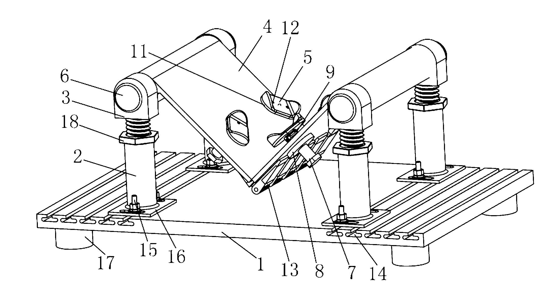
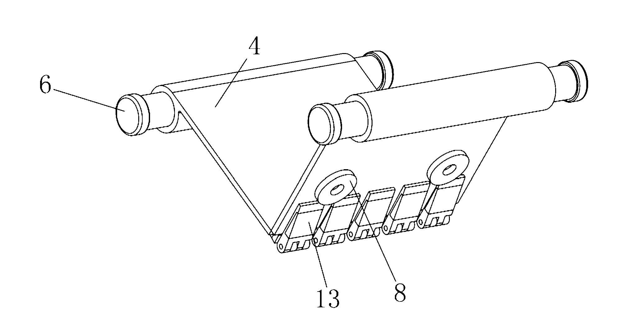
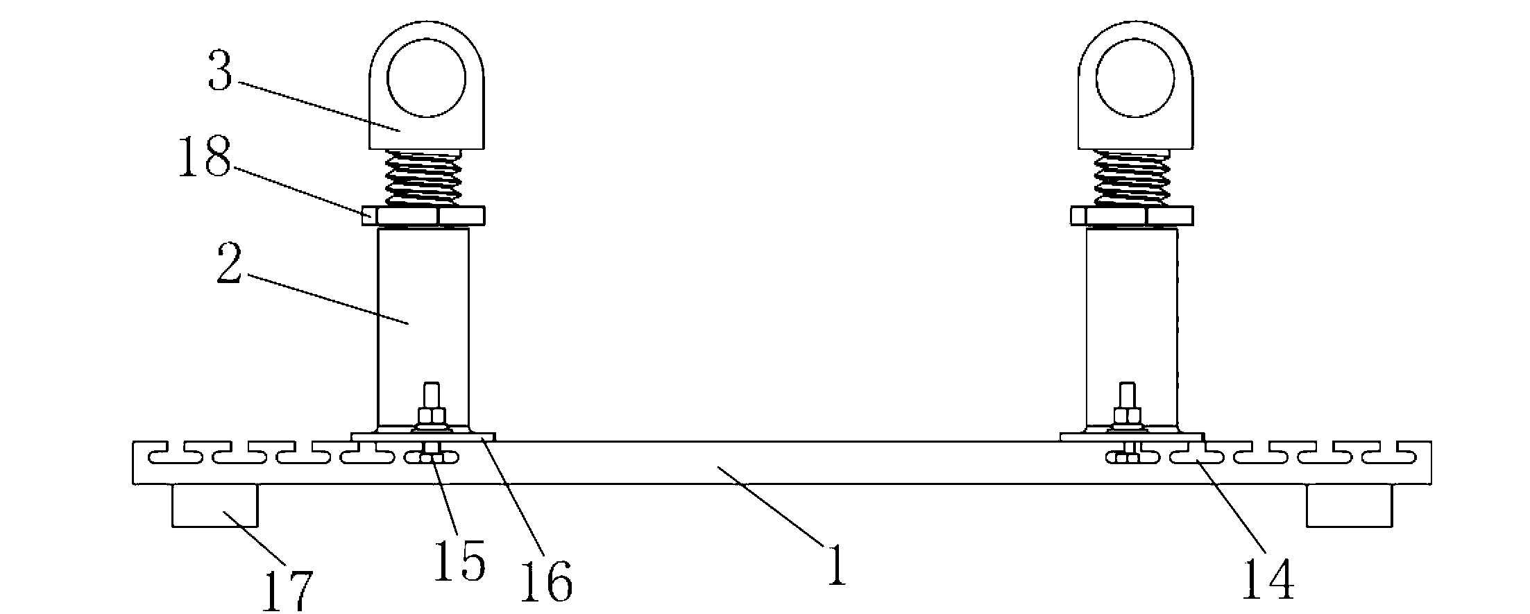
[0027] See Figure 1 to Figure 5 As shown, the new energy vehicle motor V-type installation and adjustment device of the present invention includes a base plate base 1, four screw leg bases 2, four screw legs 3, two supporting plates 4 and at least two thrust rubbers 5 , the four screw leg bases 2 are symmetrically installed on the base plate base 1 in twos, and the four screw legs 3 are threadedly engaged in the four screw leg bases 2 respectively. One end of the supporting plate 4 is hinged to each other and the other end is rotatably arranged between the two screw legs 3 to form a V-shaped bracket, and at least two of the thrust rubbers 5 are respectively arranged on two on the pallet 4.

[0028] Specifically, the supporting plate 4 can adopt No. 45 steel p...


PUM


Abstract

The invention relates to a new energy automobile motor V-shaped mounting adjustment device, wherein four lead screw supporting leg pedestals are arranged on a bottom plate seat in pairs in bilateral symmetry; four lead screw supporting legs are arranged in the four lead screw supporting leg pedestals through threaded engagement respectively; one ends of two carrying plates are hinged with each other, and the other ends of the two carrying plates are rotatablely arranged between two lead screw supporting legs respectively so as to form a V-shaped bracket; and at least two pieces of thrust rubber are arranged on the two carrying plates respectively. Preferably, the pieces of thrust rubber are movably arranged opposite to the carrying plates. The pedestal seat is provided with a plurality of parallel mounting grooves; and the four lead screw supporting leg pedestals are arranged in two of the mounting grooves in pairs in bilateral symmetry. The new energy automobile motor V-shaped mounting adjustment device has the advantages of skillful design, suitability for mounting motors of various types and sizes, capabilities of accurately controlling the inclination angle of the motor, stability and safety in mounting, accuracy, easiness, convenience, capabilities of greatly simplifying a mounting process, reducing investment in manpower and material resources, reducing the adjustment frequency and greatly increasing the working efficiency and suitability for large-scale generalization and application.

Description

technical field [0001] The invention relates to the technical field of new energy vehicle installation and adjustment tools, in particular to the technical field of new energy vehicle motor installation and adjustment devices, and specifically refers to a new energy vehicle motor V-shaped installation and adjustment device. Background technique [0002] The traditional motor installation method uses a liftable forklift, places the motor on the platform of the lift truck, fixes the motor with square bars and compares it with the mounting holes of the actual vehicle chassis, and completes the installation process after multiple adjustments. The problems that arise during this installation process are: first, the motor has a large dead weight, and the inclination angle on the vehicle cannot be accurately controlled; second, although the motor is fixed by a square bar and no longer rolls over, it cannot be adjusted when the forklift moves and adjusts. In the process, the square ...

Claims


Application Information

Patent Timeline
Patent Type & Authority Applications(China)
IPC IPC(8): B62D65/10
Inventor 程明福刘楠祝景峰
Owner JIANGXI B ENERGY SHANGRAO COACH
Why Eureka
Try Eureka